AC Power Module
Required Tools and Materials
|
|
Socket (8 mm and 13 mm) |
|
Torque wrench |
|
|
Module lifter |
|



Installing the AC Power Module requires at least two people.
Before You Begin
-
Wait at least five minutes for energy to dissipate.
After replacing the components, reverse the above steps to complete the service.
-
Complete the post-service checklist. The checklist is available at ChargePoint Product Reference Documentation.
-
Contact ChargePoint regarding faulty part return.
Remove the Safety Covers
Carefully remove the following safety covers:
External DC Bus Bars Safety Cover - Exhaust Side
Perform the following actions on the exhaust (left) side of the cabinet:
-
Loosen (do not remove) the M5 nuts (x5) that secure the DC bus bar safety cover.
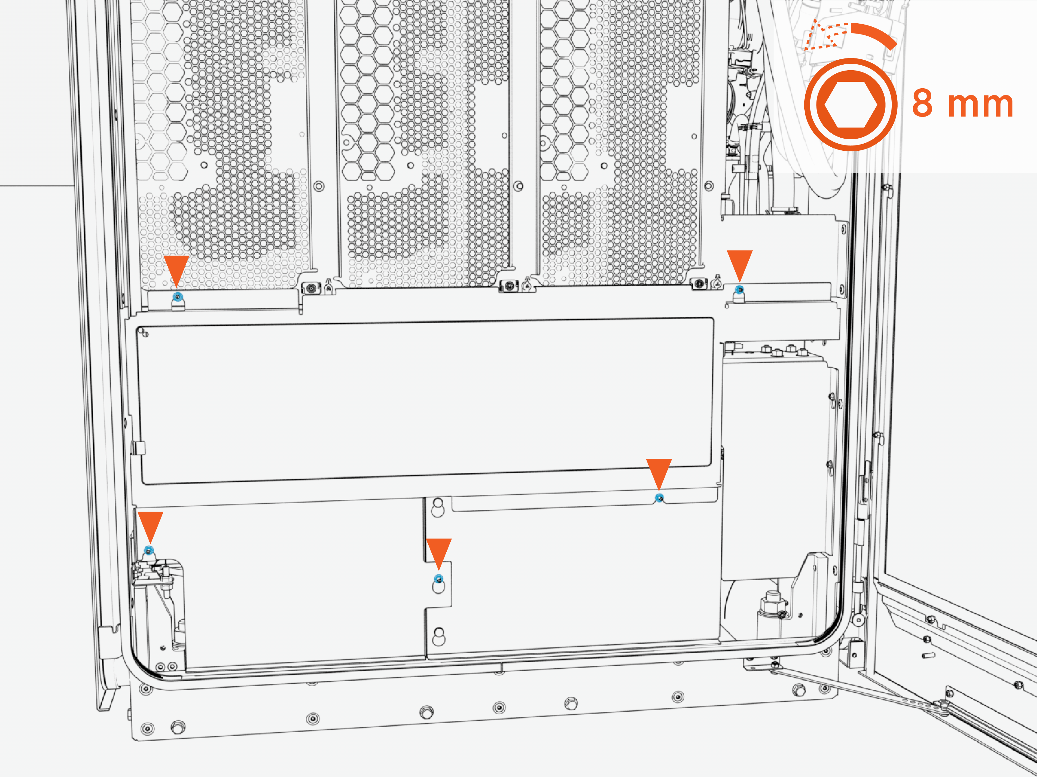 Torque the nuts to 4.5 Nm (40 in-lb).
Do not use impact driver to tighten fasteners.
-
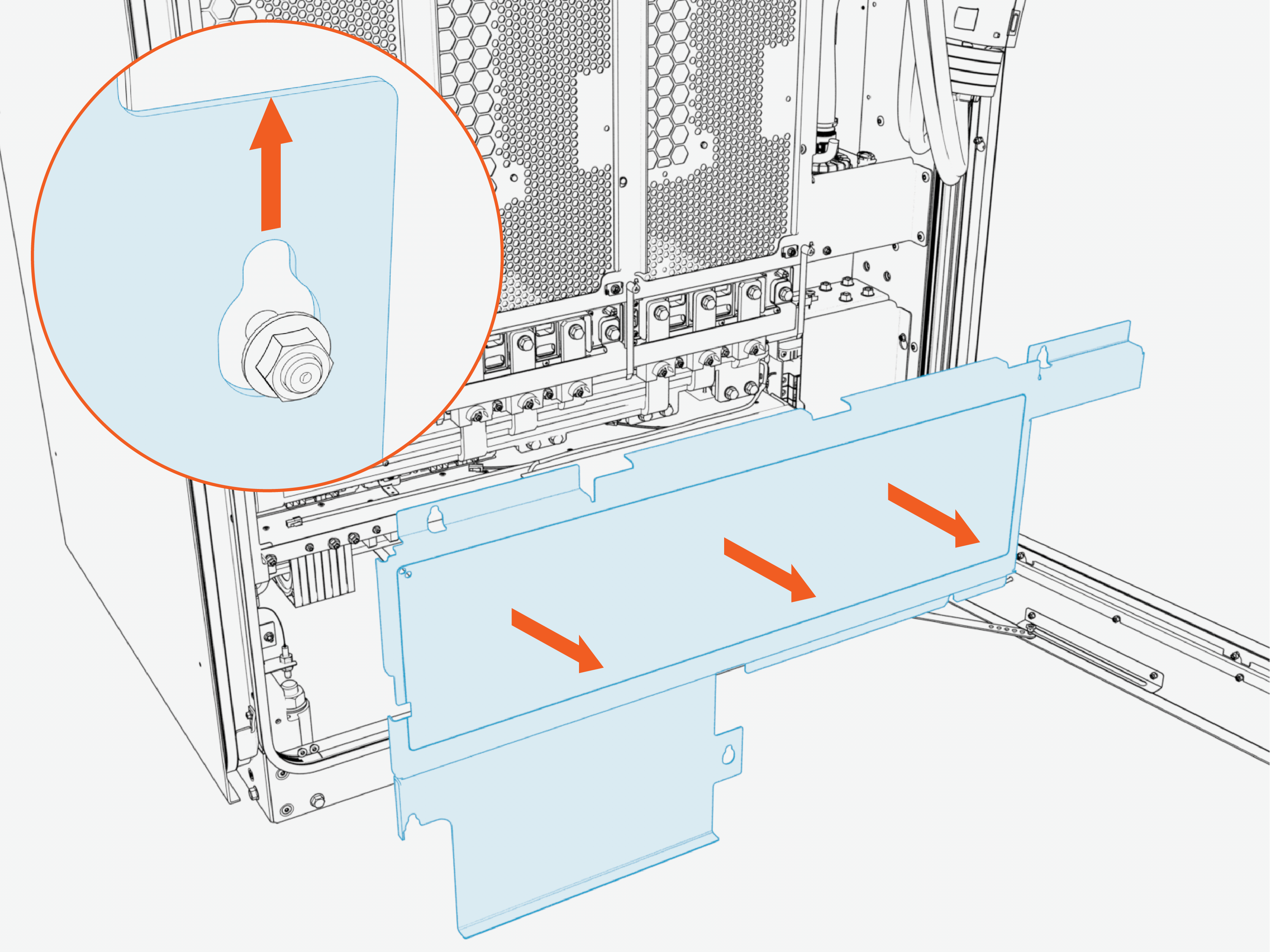
Slide the cover upward to release the keyholes. Then pull forward to remove the safety cover.
-
Reverse the above steps to reinstall the safety cover after service.
DC Grid Safety Cover
Perform the following actions on the exhaust (left) side of the cabinet:
-
Loosen (do not remove) the M5 nuts (x5).
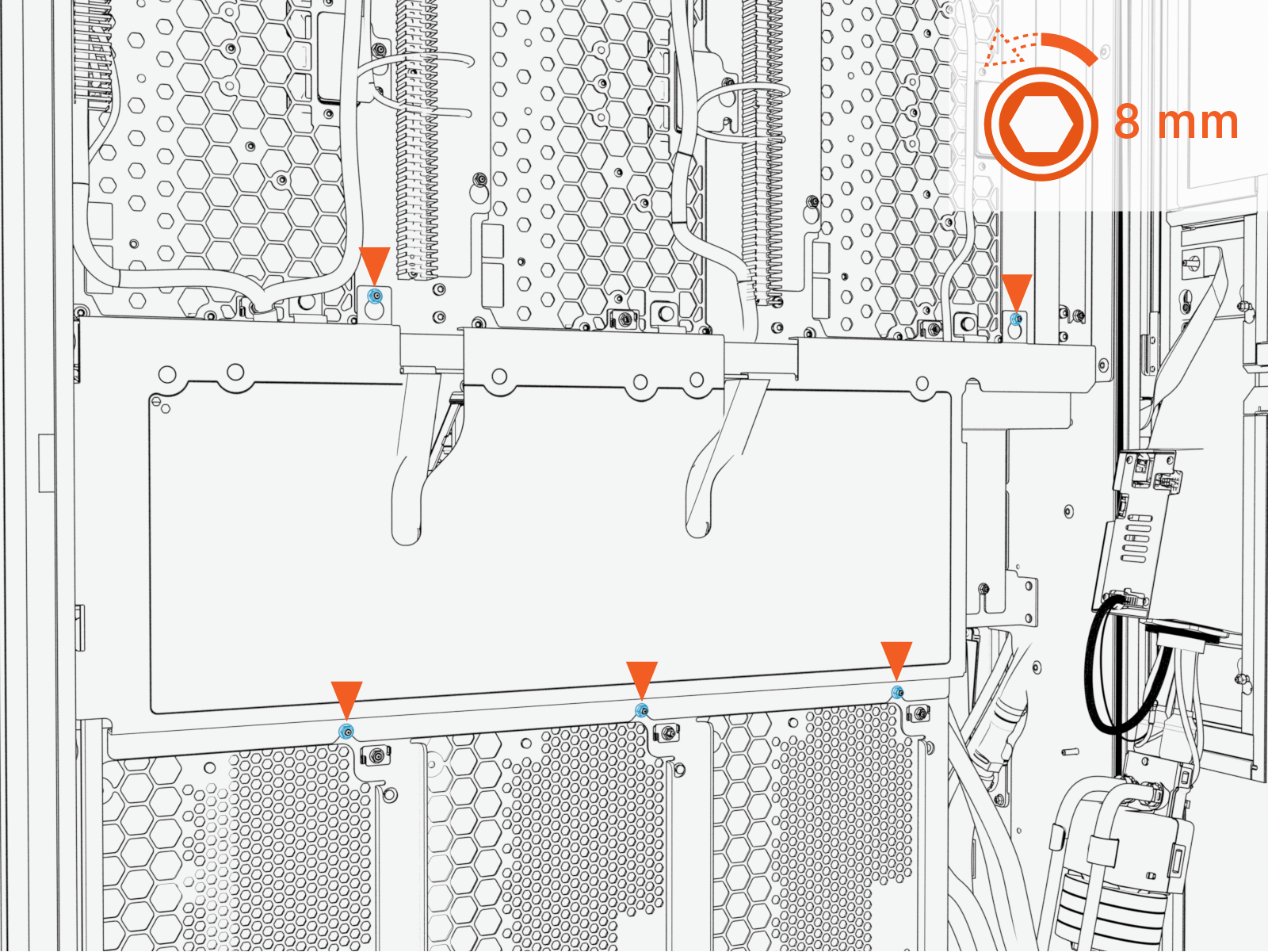 Torque the nuts to 4.5 Nm (40 in-lb).
Do not use impact driver to tighten fasteners.
-
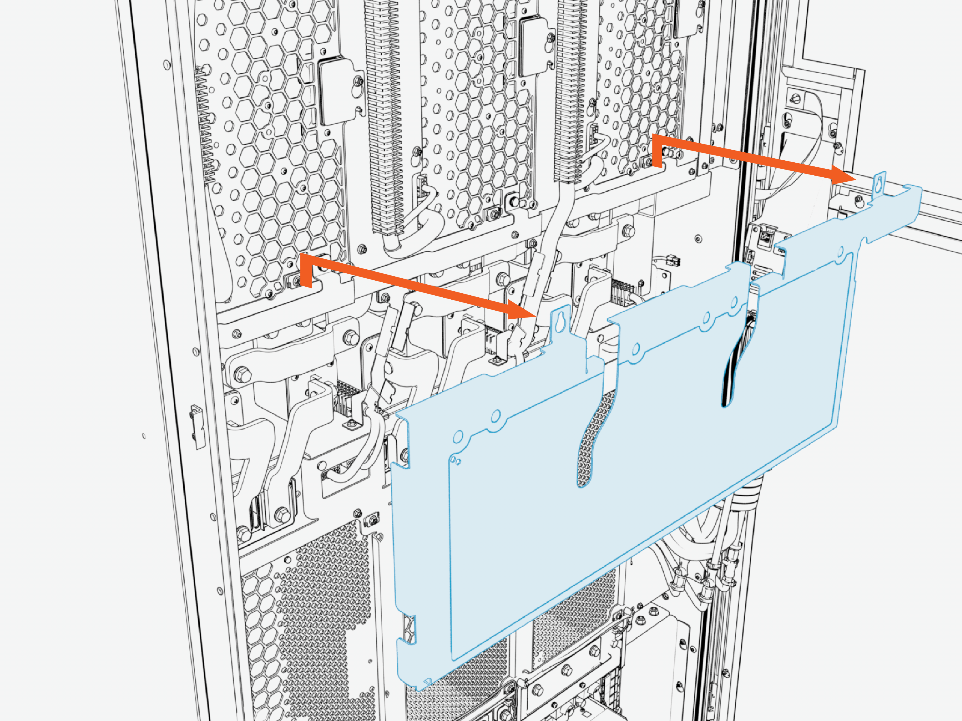
Lift the DC grid safety cover upward from the keyslot and pull it forward to remove.
-
Reverse the above steps to reinstall the safety cover after service.
Identify Target AC Power Module
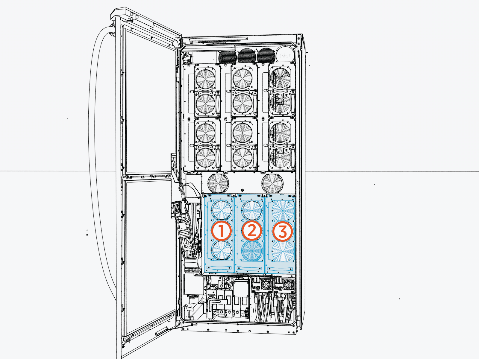
Remove the AC Power Module
To remove the AC power module for replacement, follow these steps:
-
Perform the following actions on the exhaust (left) side of the cabinet:
-
Remove the M8 bolts (x4) from the bus bars. Keep the bolts for reuse.
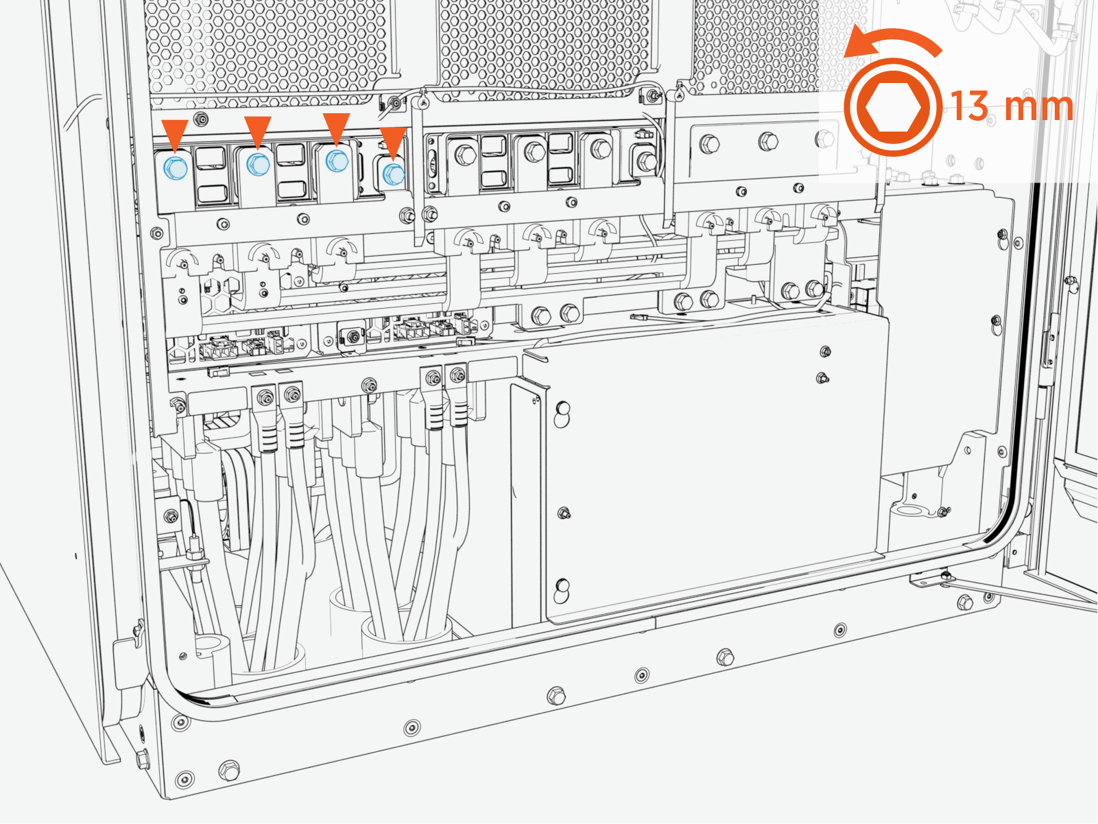 Torque the bolts to 12.2 Nm (108 in-lb). Mark all torqued bolts.
Do not use impact driver to tighten fasteners.
-
Disconnect the neutral cable. If the connector is stuck, first push the connector in, then depress the thumb tab, then pull the connector out.
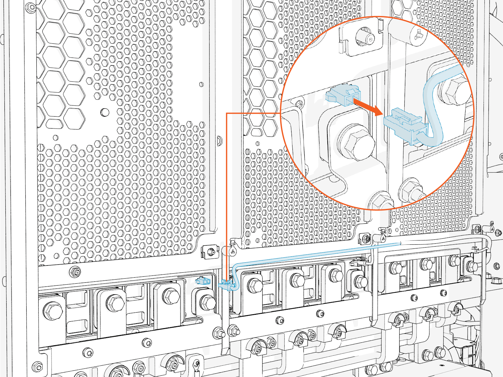
-
Remove the M8 bolts (x2) from the AC power module DC output positive (+) and negative (-) terminals.
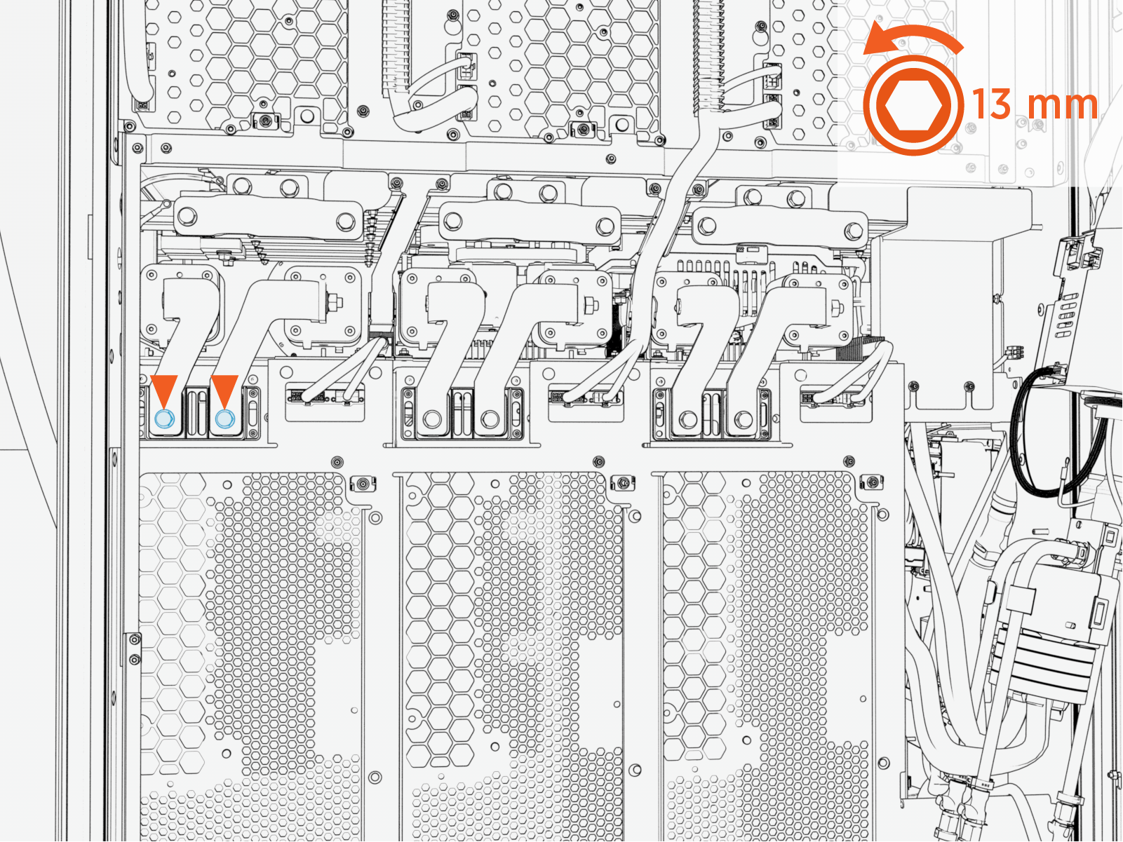 Torque the bolts to 12.2 Nm (108 in-lb). Mark all torqued bolts.
Do not use impact driver to tighten fasteners.
-
Disconnect the low-voltage connectors.
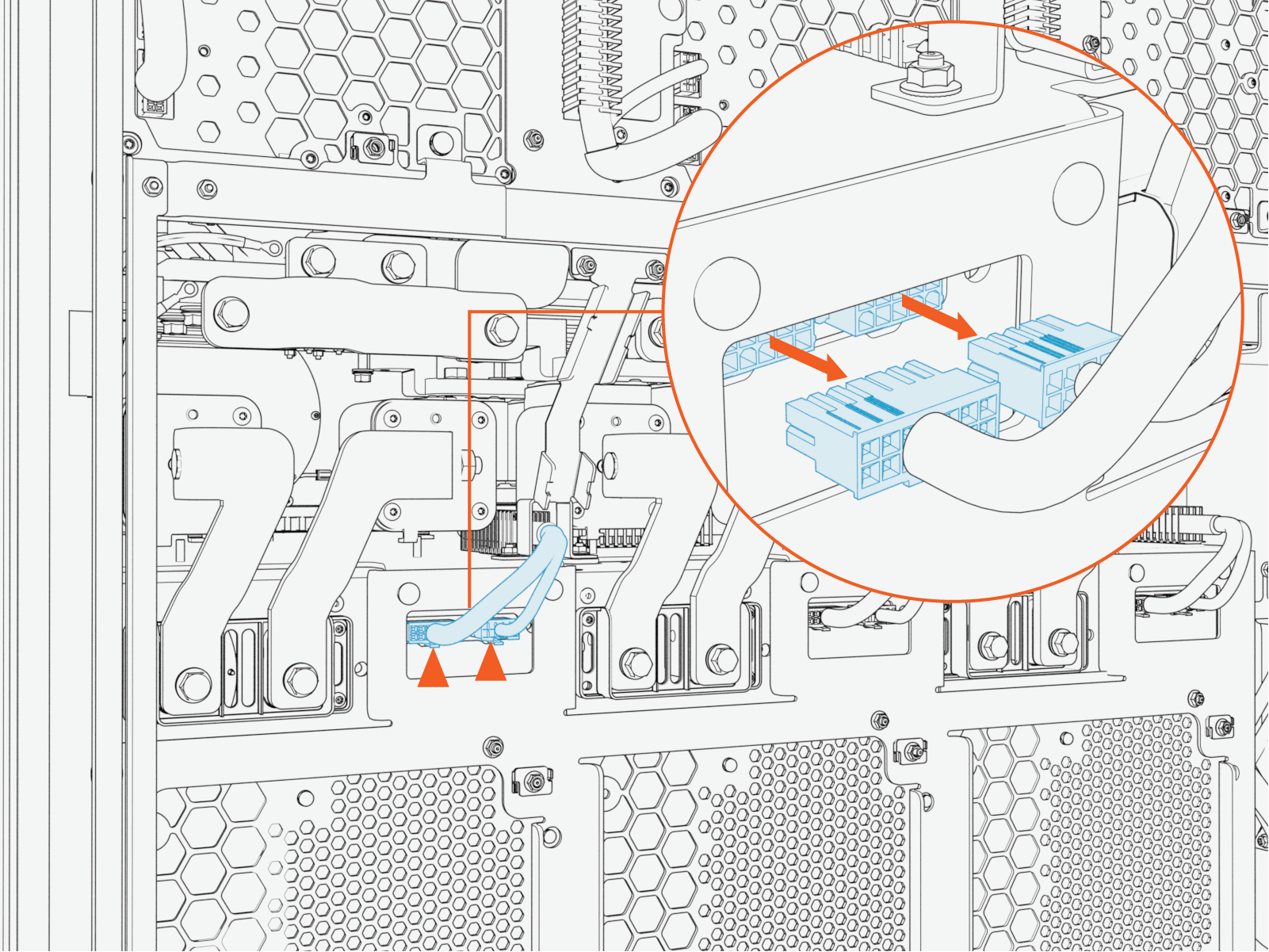
-
Remove the M5 nuts (x2) from the lower backplate.
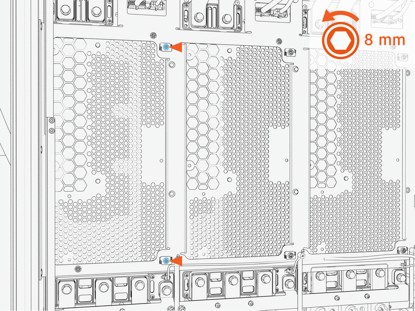
When reinstalling, hand-tighten the M5 nuts onto the threaded studs first. Then use a tool to torque the nuts to the specified torque value.
Torque the nuts to 4.5 Nm (40 in-lb).Do not use impact driver to tighten fasteners.
-
-
Perform the following actions on the intake (right) side of the cabinet:
-
Remove the M5 nuts (x2) from the AC power module enclosure.
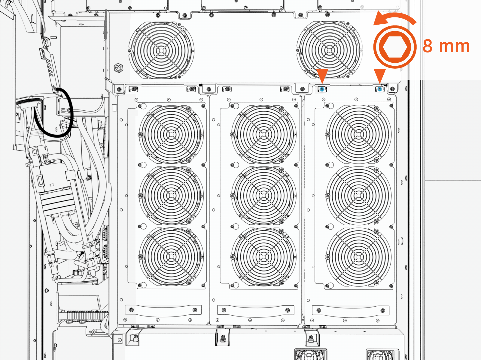 Torque the nuts to 4.5 Nm (40 in-lb).
Do not use impact driver to tighten fasteners.
-
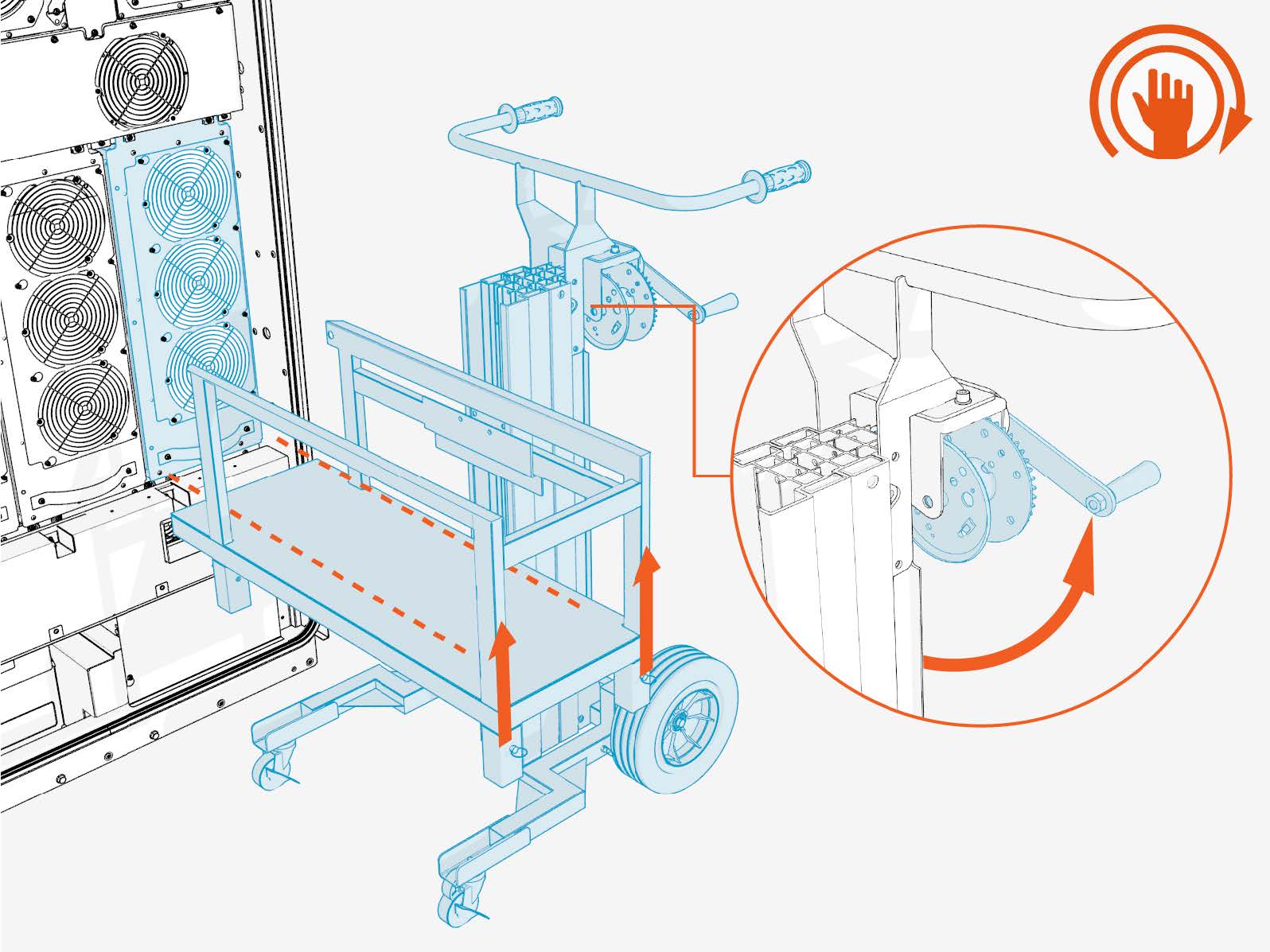
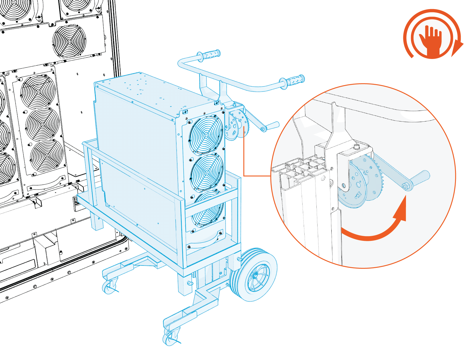
Position the module lift to support the faulty module as the module is slid out of the enclosure. Use the module lifter to support the AC power module, crank the shaft to raise the platform from lower to higher level.
Align the lift platform with the bottom of the module. Do not allow the module to drop onto the lift. The module weighs approximately 93 kg (205 lb), and shall be slid onto the lift cart in a controlled manner. Misalignment may cause the module to drop, resulting in injury or equipment damage.
Use extreme care when positioning the module lift and when raising or lowering the module. Do not allow any part of the module lift, module, or lift hardware to contact the Express Solo cabinet. Exercise additional caution when servicing modules adjacent to the cabinet door, as door-mounted components can be easily damaged by even minor contact or impact.
-
Position a person on the exhaust (left) side of the cabinet. This person will assist with pushing the module out of the cabinet (next step).
-
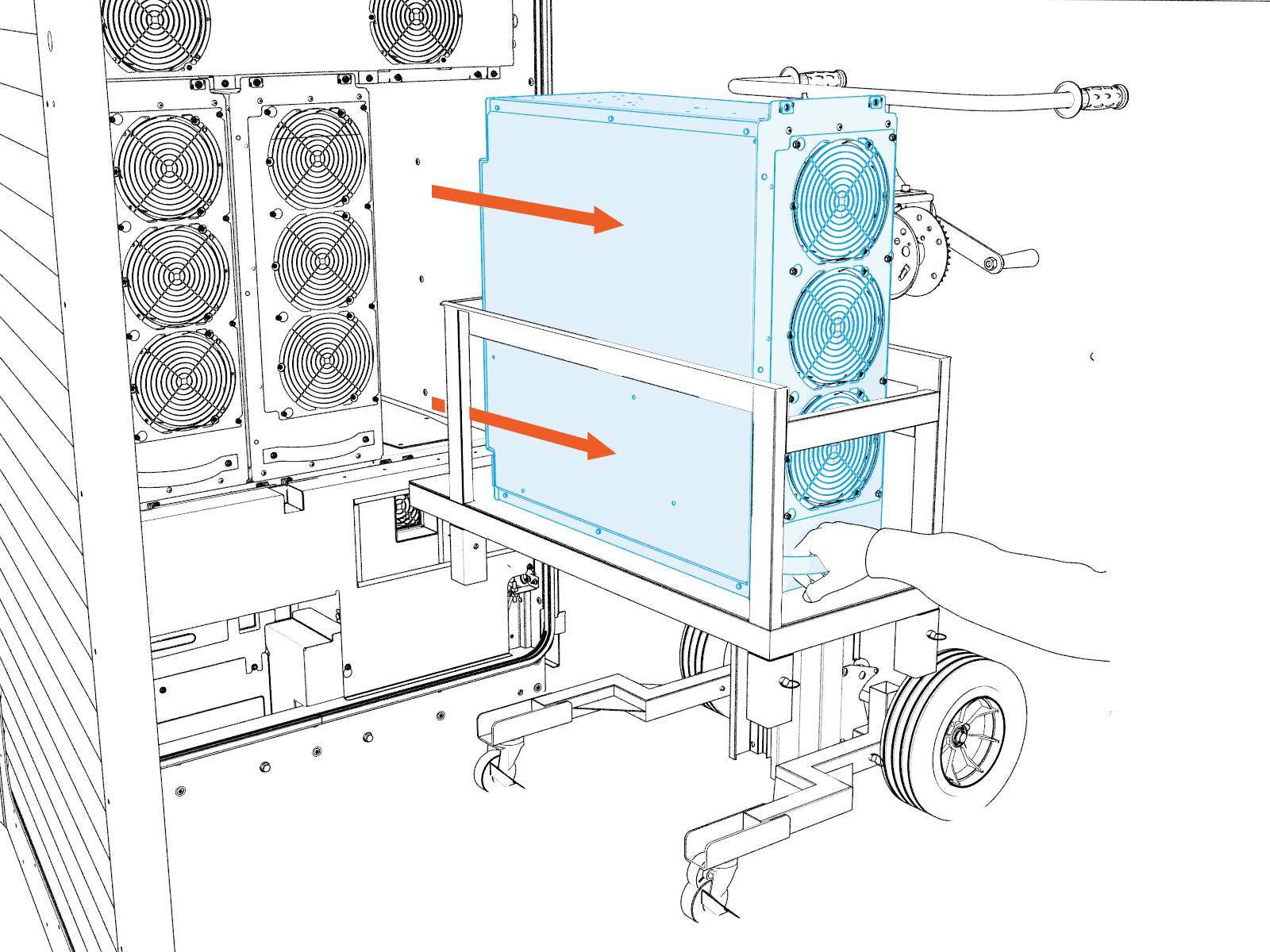
Pull the AC power module straight out of the enclosure and support the module in the lifter platform.
Before sliding out the module, verify that all cables and connectors are disconnected. Moving the module while connected can result in equipment damage.
-
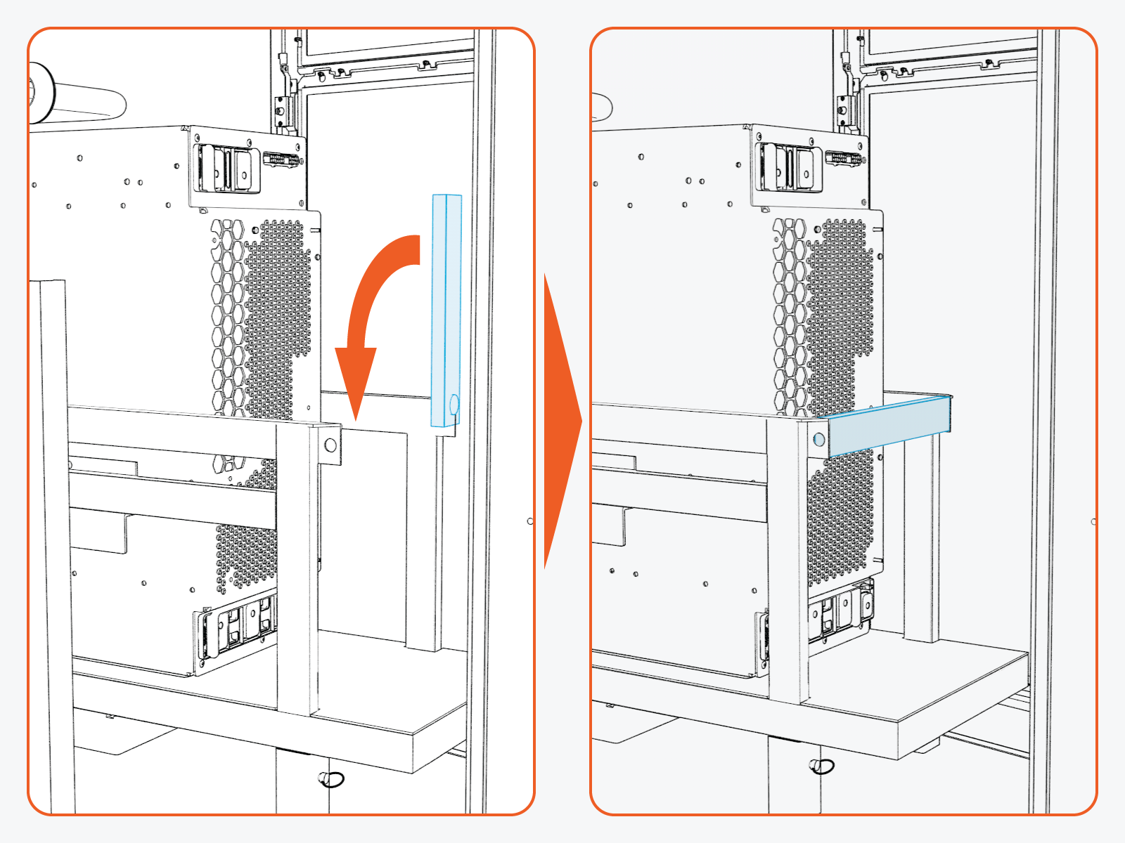
Lock the module lifter platform.
-
Once the module is fully supported by the module lift platform, verify that sufficient clearance exists between the platform and all cabinet components. If necessary, carefully move the module lift away from the enclosure to provide adequate clearance. Then lower the platform to its lowest position before transporting the module.
Lowering the platform reduces the center of gravity and helps prevent cart tip‑over when traveling over uneven surfaces.
-
Installation of AC Power Module
-
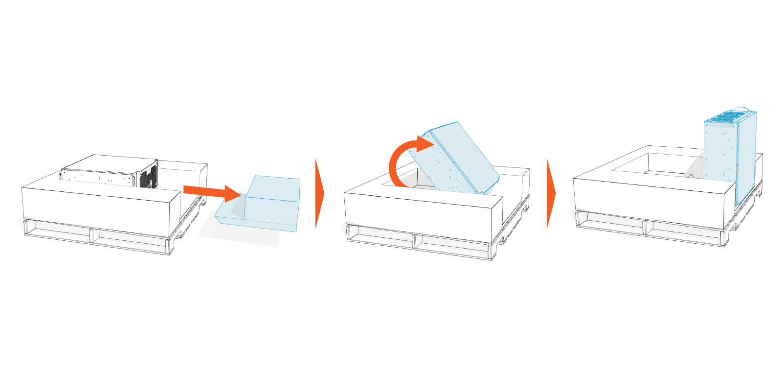
Unpack the new AC power module from the crate.
-
Remove the foam pad and rotate the AC power module vertically.
-
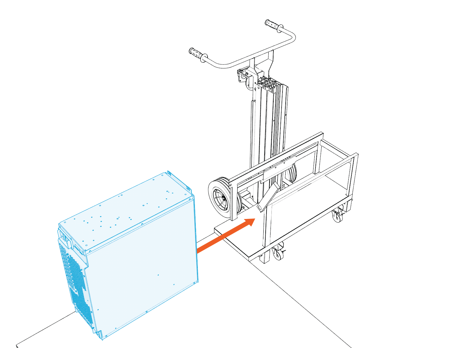
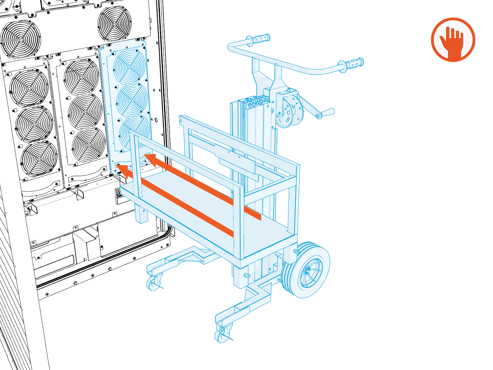
Slide the AC power module onto the module lifter at lower carrier position.
-
Position the lift in front of the empty bay, and then use the crank shaft to raise the AC power module so that it is level with the bay.
-
Position a second person on the other side of the cabinet (the exhaust/left side of the cabinet). This person will assist monitor the module as it is installed into the cabinet.
-
Slide the AC power module most of the way into the bay, leaving only the last 2 inches hanging out of the bay.
-
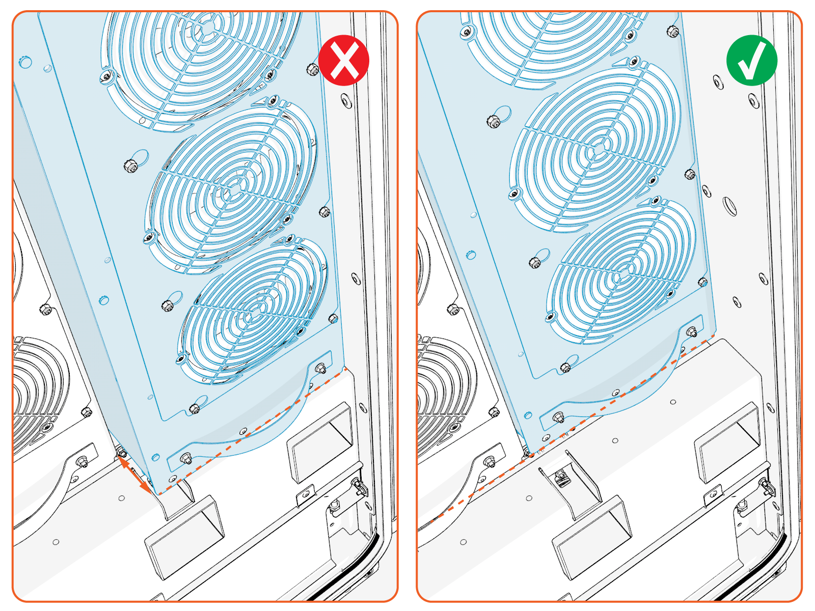
When moving the replacement module from the lift cart into the bay, do not allow the module weight to rest on the AC safety cover. The AC safety cover is not designed to support load.
-
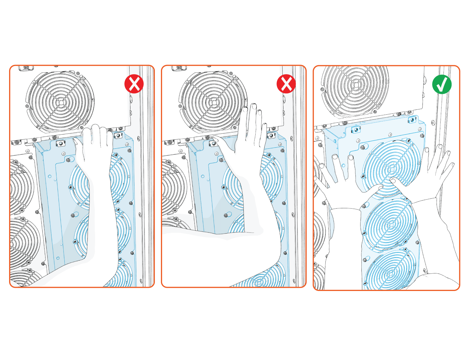
After ensuring the module is stable in the bay, remove the lift from the work area and position yourself in front of the module. Push the module fully into the bay.
The module is heavy and can cause injury if handled improperly. Keep hands and fingers clear of pinch points when sliding the module into the bay. To avoid damaging the module, do not apply pressure to the fan grilles. Push the module into position using only the solid frame.
-
Reverse the removal procedure to reconnect all cables, terminals and bus bar connections.