Configure Cable (Circuit) Sharing
Cable sharing refers to a single circuit supplying power to two ports on the station.
CP6000 charging stations can be installed with single cable feeding both ports (circuit share) or with dual cables, one for each port.
For assistance, go to chargepoint.com/support and contact technical support using the appropriate region-specific number. Order power management jumpers from Support if required.
CP6000 charging stations comes with two options:
Residual Current Circuit Breaker (RCCB
 Residual Current Circuit Breaker) per charging port or
Residual Circuit Breaker with Overload Protection (RCBO
Residual Current Breaker with Overload Protection) per charging port
Talk to your local ChargePoint contact and agree on the best solution for the installation.
When choosing RCBO![]() Residual Current Breaker with Overload Protection, a single input cable can be supplied to the charging station because of the share power management jumpers. The upstream cable will also be protected according to the national wiring regulations.
Residual Current Breaker with Overload Protection, a single input cable can be supplied to the charging station because of the share power management jumpers. The upstream cable will also be protected according to the national wiring regulations.
When choosing RCCB![]() Residual Current Circuit Breaker in certain countries, local wiring regulations will require that these stations shall be connected with two input power cables and an additional upstream Miniature Circuit Breaker (MCB
Residual Current Circuit Breaker in certain countries, local wiring regulations will require that these stations shall be connected with two input power cables and an additional upstream Miniature Circuit Breaker (MCB![]() Miniature Circuit Breaker). Make sure to follow the local regulations considering the maximum current delivered per charging port.
Miniature Circuit Breaker). Make sure to follow the local regulations considering the maximum current delivered per charging port.
If an upstream RCD![]() Residual Current Device will be used, ensure that the RCD
Residual Current Device will be used, ensure that the RCD![]() Residual Current Device fulfills the selectivity criteria. Either 30 mA (s) with selective tripping characteristic or 100 mA are required so both RCDs (RCCB
Residual Current Device fulfills the selectivity criteria. Either 30 mA (s) with selective tripping characteristic or 100 mA are required so both RCDs (RCCB![]() Residual Current Circuit Breaker in station and RCD
Residual Current Circuit Breaker in station and RCD![]() Residual Current Device in upstream circuit board) will be connected in series.
Residual Current Device in upstream circuit board) will be connected in series.
-
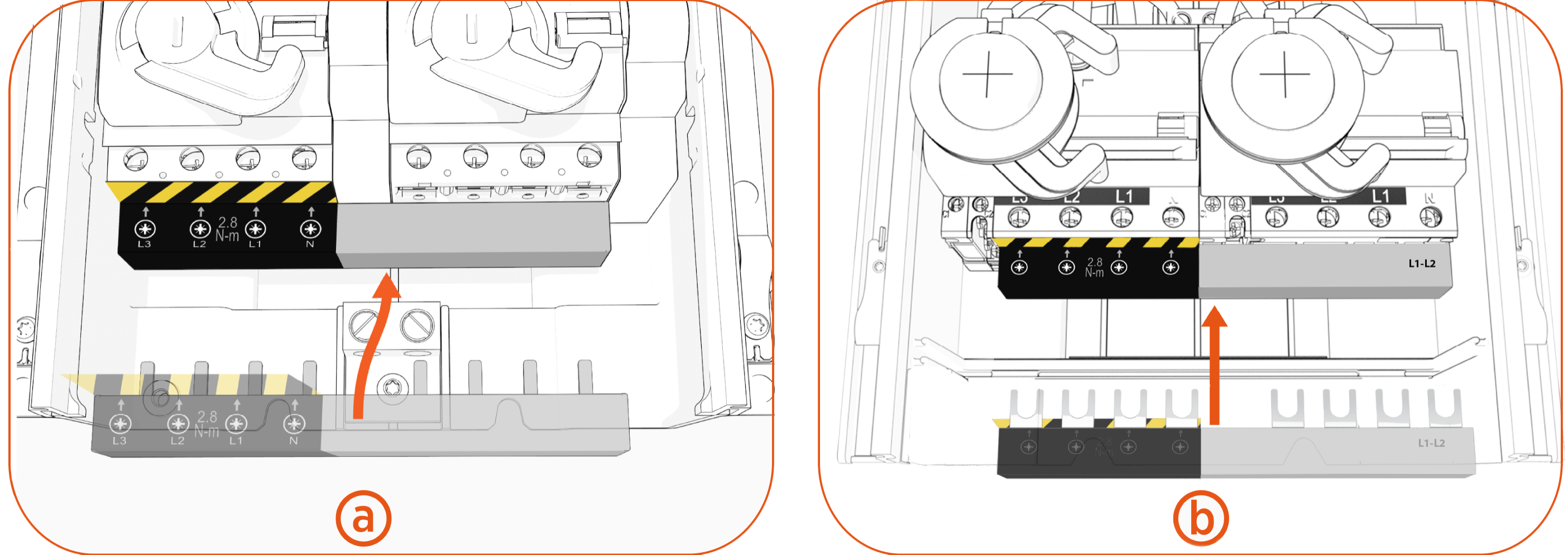
Slide the power plate cover up and gently set it aside.

-
Install the jumper.
Jumpers for RCBO Residual Current Breaker with Overload Protection and RCCB Residual Current Circuit Breaker breakers look slightly different; however, the installation and wiring are the same.
-
Measure the diameter of the wires.
-
Snip holes in the nubs on the black rubber shield.
Holes must be at appropriate heights to allow wiring to pass through the rubber shield and into the terminal block.

-
Ensure the wires can slide through the holes after snipping the nubs.
