Guidelines for Stations Supplied With Single Phase Power
When installing a CP6000 station as a single phase station, be aware of the following considerations:
Panel type
-
Select 1 phase for a single phase station setup.
During the installation, the installer can choose the panel type as a 1 phase or a 3 phase.
Number of input (power) cables wired to the station
-
Dual port with a single power cable
-
Dual port with a dual power cable: Each port has its own power cable, so no circuit share power management jumper is required.
-
For cloud-based power management (if applicable): For cloud-based power management hosted by ChargePoint, ensure both ports use the same phase, even if supplied by two different cables. Stations not using power management can have different phases for each port.
- Avoid any phase rotation between ports. Stations with phase rotation cannot support single phase cloud-based power management.
-
Do not use a single 5-wire cable to supply both ports with different phases. This setup is not supported and may lead to undesirable behavior. Contact ChargePoint if this is the only available option.
-
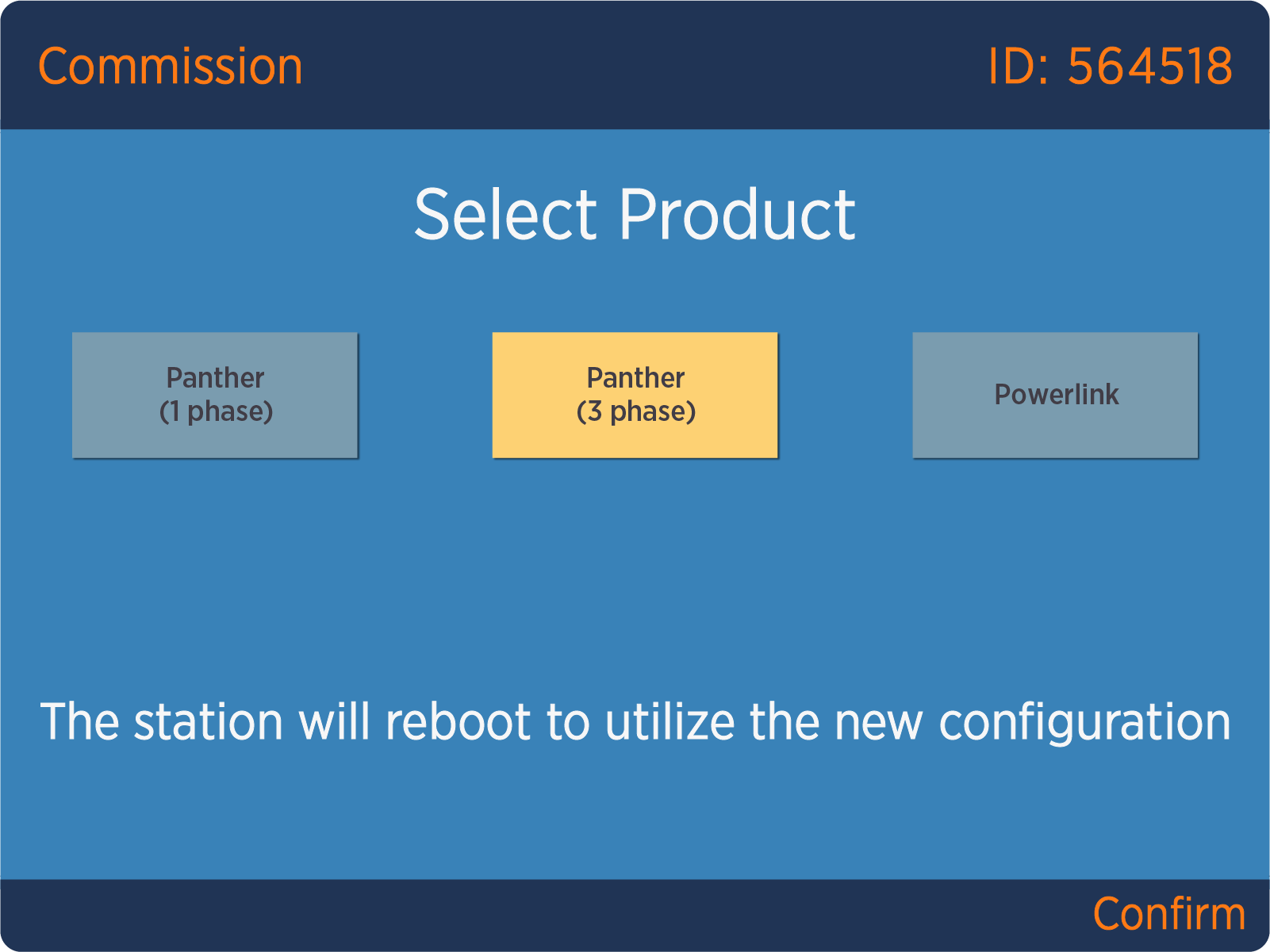
If presented with the Commission page when configuring the station as 1 phase, select the 3 phase station option. This only indicates that all EU CP6000 stations are 3 phase capable, even if wired as a single phase station. If the 1 phase option appears (as highlighted), this further indicates that the EU station is incorrectly identified and must be corrected before proceeding.
Wiring Diagrams for Single Phase Installation
These diagrams show wiring for installing single and dual port CP6000 stations on:
-
A dual circuit, dual port
-
A single circuit, dual port
-
A single circuit, single port
The number of dedicated circuits required depends on the type of installation and the power available at the site.
Refer to the CP6000 Datasheet on ChargePoint Product Reference Documentation for electrical input and output specifications.
230 VAC Single Phase Dual Circuit, Dual Port

(a) L1
(b) Neutral
(c) Main breaker
(d) Neutral bus
(e) Ground bus
(f) Left breaker
(g) Right breaker
(h) Ground
(i) Wire strip length 12 mm (0.5 in)

230 VAC Single Phase Single Circuit, Dual Port

(a) L1
(b) Neutral
(c) Main breaker
(d) Neutral bus
(e) Ground bus
(f) Breaker
(g) Ground
(h) L1 - L1 jumper
(i) Wire strip length 12 mm (0.5 in)

230 VAC Single Phase Single Circuit, Single Port

(a) L1
(b) Neutral
(c) Main breaker
(d) Neutral bus
(e) Ground bus
(f) Breaker
(g) Ground
(h) Wire strip length 12 mm (0.5 in)

