Replace the Power Plate
This chapter covers replacing a power plate. The power plate can have either an RCCB![]() Residual Current Circuit Breaker or a RCBO
Residual Current Circuit Breaker or a RCBO![]() Residual Current Breaker with Overload Protection.
Residual Current Breaker with Overload Protection.
Required Tools and Materials
|
|
Torx screwdriver (T25) |
|
|
4 mm hex wrench
|
Remove the Head Assembly
Perform the following steps to remove the head assembly:
-
Use your ChargePoint card or the mobile app to start a charging session, unlock the charging cables, and set them gently down.

-
Disconnect the power to the CP6000 at the service panel.
Risk of shock
-
Before any procedure, the technician must disconnect the power.
-
Follow local code to de-energize the applicable circuit and lock out/tag out the disconnect before proceeding. Use a multimeter to test that power is off.
-
Keep power off until the top cap is correctly reinstalled and the work is complete.
Failure to follow these instructions can result in serious injury, loss of life, or property damage.
-
-
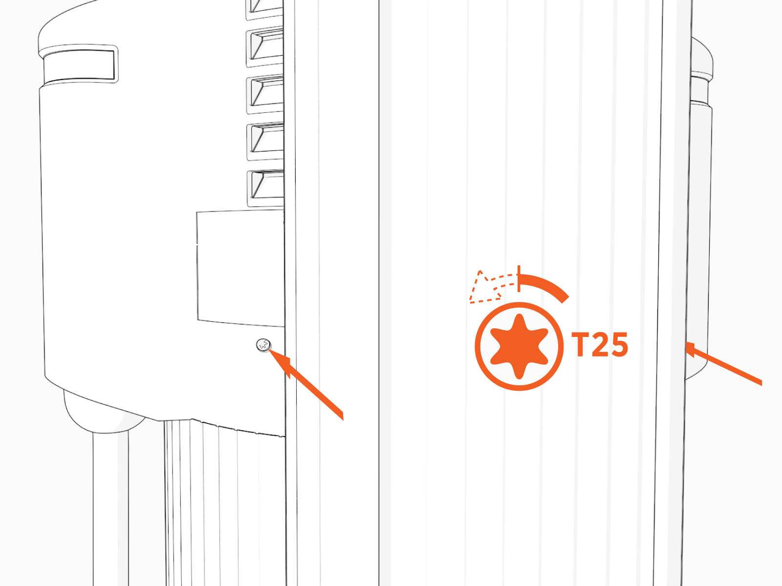
Use the L-wrench to loosen the two T25 screws securing the top cap.
-
Remove the top cap.

-
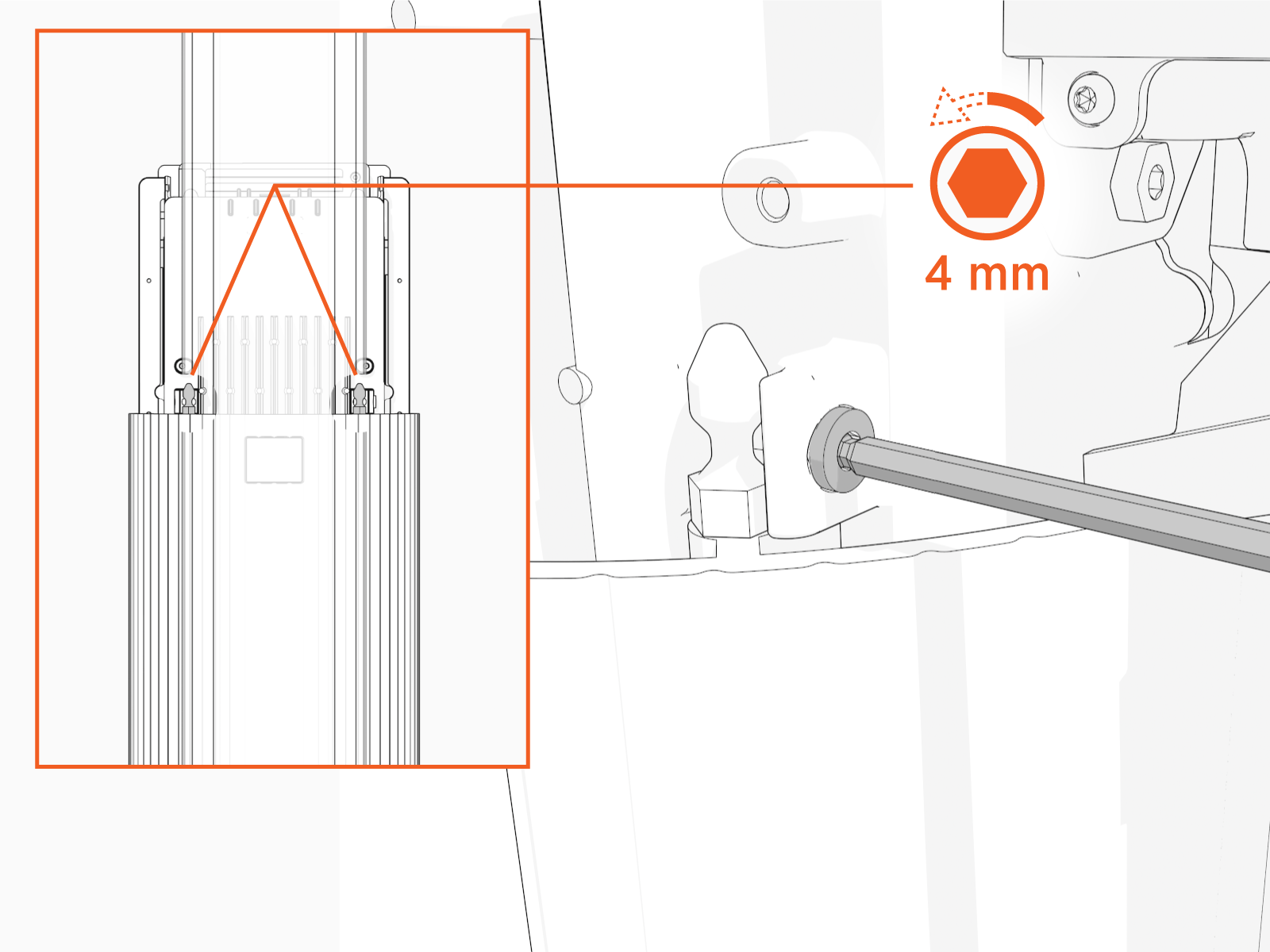
Use the L-wrench to loosen, but do not remove, the screws securing the head assembly.
-
Lift the head assembly to remove it from the pedestal or wall mount enclosure. Place it gently face down on a padded surface.

-
Slide the cover up and remove the cover from the power plate.

Remove the Power Plate
To remove the power plate, perform the following steps:
Risk of shock
-
Before any procedure, the technician must disconnect the power.
-
Follow local code to de-energize the applicable circuit and lock out/tag out the disconnect before proceeding. Use a multimeter to test that power is off.
-
Keep power off until the top cap is correctly reinstalled and the work is complete.
Failure to follow these instructions can result in serious injury, loss of life, or property damage.
-
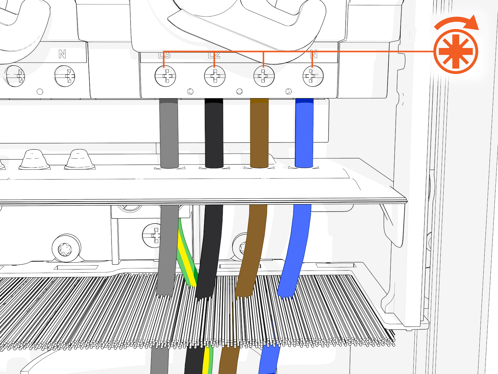
Before removing the power plate, disconnect the wiring.

-
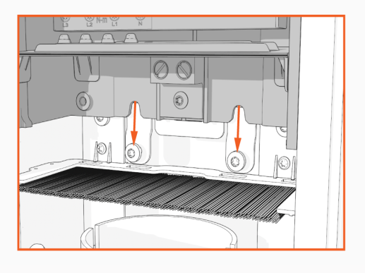
Using a T25 torque driver, loosen but do not remove screws securing the power plate.

-
With the screws still in place, carefully lift the power plate upward to remove it from the metal bracket.
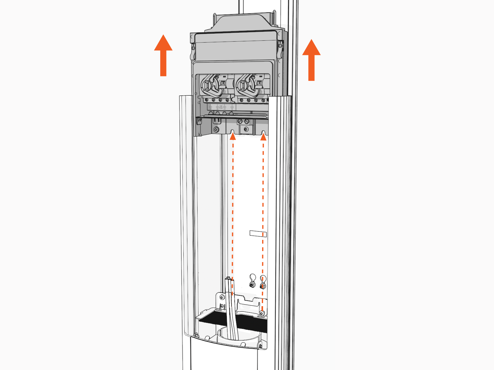 Avoid damaging the shunt trip cables when handling or removing the plate.
 -
Ensure the power plate is completely removed.
-
Verify that no components or cables are obstructed after removal.
Install the New Power Plate
Perform the following steps to install the new power plate:
-
Before you install the new power plate, remove the power plate cover.

-
Install the jumper. This step is optional and needed only if power sharing.
Jumpers for RCBO Residual Current Breaker with Overload Protection and RCCB Residual Current Circuit Breaker breakers look slightly different; however, the installation is the same.

-
Measure the diameter of the wires.
-
Snip holes in the nubs on the black rubber shield.
Holes must be at appropriate heights to allow wiring to pass through the rubber shield and into the terminal block.

-
Ensure the wires can slide through the holes after snipping the nubs.
-
-
Align the power plate with the housing and slide it down until it fully seats on the metal bracket.
 Avoid damaging the shunt trip cables when routing.
 -
Ensure the power plate is seated correctly.
-
Using a T25 torque driver, torque the screws to 5.7 Nm (50 in-lb) to secure the power plate.

-
Ensure the power plate is fully seated. Ensure the power plate is fully seated. If the distance from the top of the power plate to the top of the pedestal does not equal 286 +/- 1 mm (11.26 in) (a), contact ChargePoint Support.

-
Reconnect the wiring before installing the power plate cover.
 Ensure to turn ON the breaker. If you previously unplugged the Ethernet cables, make sure to plug them back in.
 -
Install the power plate cover.

-
Align the rails on the head assembly with the pedestal and slide all the way into the pedestal housing.

-
Ensure the head assembly is fully seated.

-
Using the L-wrench, hand tighten the two screws.

-
Slide the top cap onto the head assembly, adjusting as necessary to clear the charge cables, until it fits into place.

-
Torque two captive screws to 1.1 Nm (10 in-lb).

-
Insert the charging cables into their corresponding holsters.

-
At the electrical panel, power up the station.
One or both port LEDs appear Red until the lockout faults are cleared.
Next Steps
Clear Lockout Faults
When you replace a part, the station triggers lockout faults.
To clear lockout faults, go to chargepoint.com/support and contact technical support using the appropriate region-specific number.
