Replace a Holster

For assistance, go to chargepoint.com/support and contact technical support using the appropriate region-specific number.
Required Tools and Materials
|
|
Torx screwdriver (T25) |
|
|
4 mm hex wrench
|
|
|
Padded surface |
Replace a Standard Holster
If the CP6000 has a standard holster, follow the instructions in this section to replace the current holster frame with a new Omni Port holster frame assembly.
Before You Begin
Review of Omni Port Components and Connections
|
|
|

Remove the Charging Cables
To remove the charging cables, perform the following steps:
-
Use your ChargePoint card or the mobile app to wake the station up.
If the station does not have power, contact the station owner to learn when power will be available and discuss appropriate next steps.If you do not have a ChargePoint account, go to chargepoint.com/support, find your region's technical support number, and contact ChargePoint Support.
-
Unlock the charging cables and set them down gently.
-
Disconnect the power to the CP6000 at the service panel.
-
Before any procedure, the technician must disconnect the power.
-
Follow local code to de-energize the applicable circuit and lock out/tag out the disconnect before proceeding. Use a multimeter to test that power is off.
-
Keep power off until the top cap is correctly reinstalled and the work is complete.

Risk of shock
Failure to follow these instructions can result in serious injury, loss of life, or property damage.
Remove the Head Assembly
To remove the head assembly, perform the following steps:
-
Use the L-wrench to loosen two captive screws securing the top cap.

-
Remove the top cap.

-
Use the L-wrench to loosen, but do not remove, the screws securing the head assembly.

-
Lift head assembly and insert an L-wrench or a screwdriver through the hole on the side of the head assembly to hold the head assembly in the raised position.

-
Loosen, but do not remove, the screws that secure the Control and Communication Module (CCOM
 Control and Communications Module) to the head assembly.
  to the head assembly.")
-
Lift the CCOM
Control and Communications Module up and tilt it away from the head assembly. The bottom edge of the CCOM
Control and Communications Module rests on the upper edge of the holster assembly.
-
Remove the new holster frame assembly from the packaging.
-
The replacement holster frame (Omni Port) assembly contains the following components:
Replacement Omni Port Holster Frame 
-
Y-split CAN bus cable
-
48 V power supply cable
-
Omni Port holster cable
-
Downlight cable
-
Omni Port holster cable
-
-
Confirm all parts are present. For any missing component, contact chargepoint.com/support.
-
Remove the Y-split CAN cable from the new holster.

-
Unplug the 16-pin male connector from the CCOM
Control and Communications Module..")
-
Plug the 16-pin male connector into the 16-pin female side of the Y-split CAN cable.
-
Plug the 16-pin male connector from the Y-split cable into the port where you originally removed the 16-pin male connector from the CCOM
Control and Communications Module. 
-
Unplug the three-pin power connector from the CCOM
Control and Communications Module.
-
Plug the three-pin power connector on the Y-split cable (a) into the CCOM
Control and Communications Module.Connect other end of the Y-split power cable to the CCOM
Control and Communications Module power connector (b) removed in the previous step.  into the CCOM. Connect other end of the power cable to the CCOM power connector (b) that you removed in the previous step.")
-
Ensure the other end of the Y-split CAN cable is visible and accessible for connecting to the Omni Port assembly later.

-
Raise the CCOM
Control and Communications Module and slide it into place on the head assembly.
-
Tighten the screws to secure the CCOM
Control and Communications Module.
-
Lift the head assembly to remove it from the pedestal or wall mount enclosure. Set it gently on a padded surface.

-
Orient the head assembly so the screen is resting directly on the padded surface.

.")
Remove the Holster Frame
To remove the holster frame, perform the following steps:
-
Use a T25 screwdriver to loosen the four thumb screws (a) securing the holster frame to the CCOM
Control and Communications Module. securing the holster frame to the CCOM.")
-
Lift the tabs and pull the downlight (a) and holster cables (b) out to disconnect them from the holster frame.
-
Downlight cable (LED)
-
Holster cables
-

-
-
Set the holster frame aside.
Install New Omni Port Holster Frame
To install New Omni Port holster frame, perform the following steps:
-
Turn the head assembly over so the screen faces up.

-
Position the new Omni Port holster frame at a 45° degree angle to the head assembly.
Connect the downlight (a), power, left and right (b), and Y-split CAN(c) cables to their corresponding ports on the CCOM
Control and Communications Module.
-
Ensure the latch on each cable is flush.

-
Route the Omni Port cable harness along the right side of the meter window.

-
Flip the meter door open.
-
Ensure the cable is not visible. Compress the cable and make sure it stays clear of the meter window.
-
Align the outer holster frame screws with the screw holes on the sides of the CCOM
Control and Communications Module. Line up the tabs and thread the bottom holes first to secure the frame in place. 
-
Position the holster frame over the head assembly.
-
Using a T25 screwdriver, torque the four M5 screws to secure the outer holster frame to the CCOM
Control and Communications Module.
Reinstall the Head Assembly
To reinstall the head assembly, perform the following steps:
-
Hold the metal edges of the head assembly and lift it gently from the padded surface.
-
Slide the head assembly all the way into the pedestal housing.

-
Ensure the head assembly is fully seated.

-
Using the L-wrench or 4 mm hex tool, tighten two screws.

-
Slide the top cap onto the head assembly, adjusting as necessary to clear the SEVC
Smart Electric Vehicle Cable cables, until it fits into place.
-
Torque two captive screws to 1.1 Nm (10 in-lb).
.")
-
At the electrical panel, power up the station.
-
Contact chargepoint.com/support to clear lockout faults. One or both port LEDs appear Red until the lockout faults are cleared.
Replace an Existing Omni Port Holster
Before You Begin
Review of Omni Port Components and Connections
|
|
|
If the CP6000 is already installed and configured with an Omni Port holster, follow the instructions in this section to replace the existing Omni Port holster frame with a new Omni Port holster frame assembly.
-
Remove the head assembly and place it gently on a padded surface.
Visit Remove the Head Assembly and complete the steps.
-
Using a T25 screwdriver, loosen the four M5 screws (x4) securing the Omni Port holster frame to the CCOM
Control and Communications Module.
-
Hinge the holster frame away from the head assembly to access the internal wiring and components of the CCOM
Control and Communications Module. -
Unplug the following power and communication cables from the Omni Port holster frame:
-
Downlight cable
-
Power cables (for left and right holsters)
-
Y-split CAN connector
-
-
Remove the Omni Port frame and set it aside.
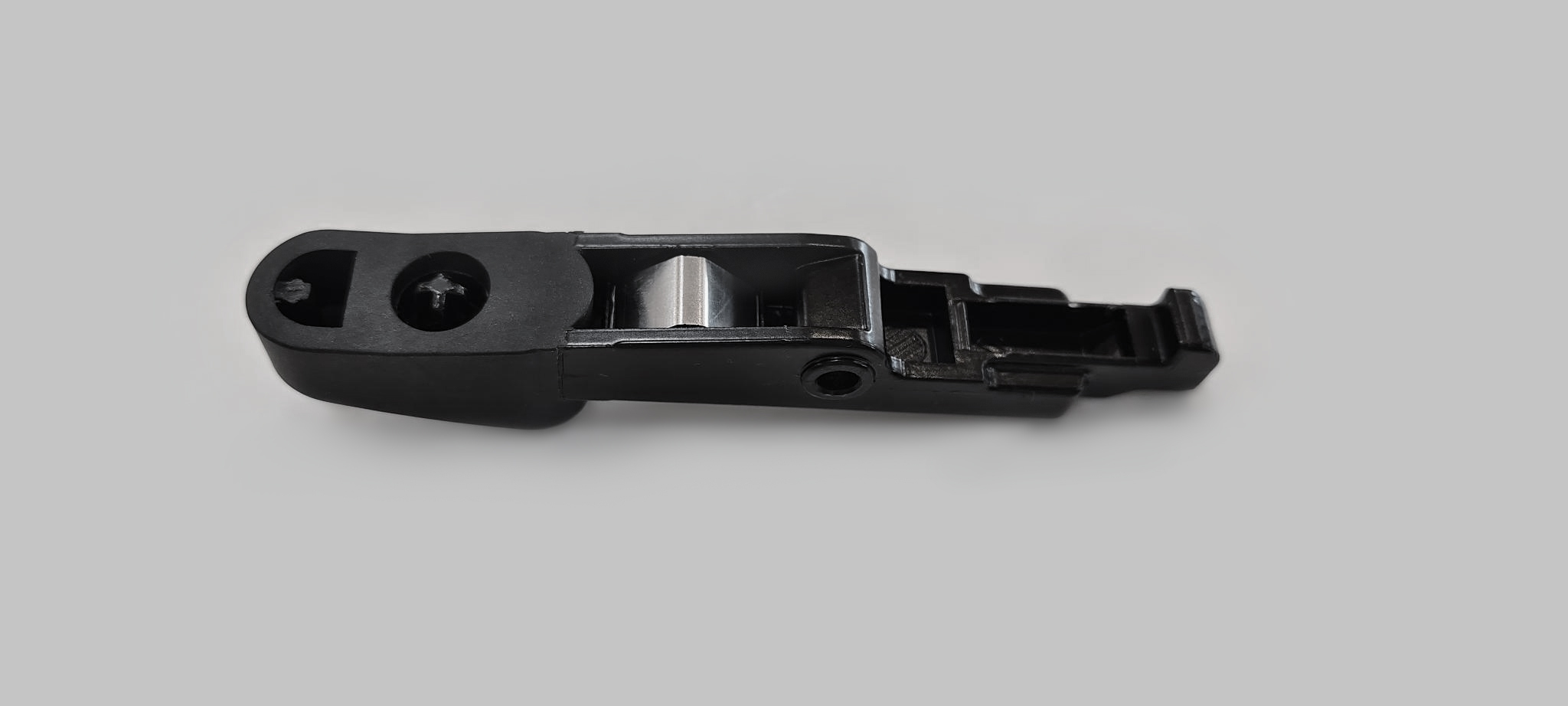
Replace a J1772 Latch
Inspect the Box for Contents
The replacement kit for J1772 connector latches includes:
-
Hex wrench
-
Repair tool
-
Drive bolt
-
Guide pin
-
Square nut (not shown)
-
Consumable latches and springs labeled for Type A and Type B connectors (not shown)

Assemble the Tool
To assemble the tool, perform the following steps:
-
Place the square nut inside the tool body.
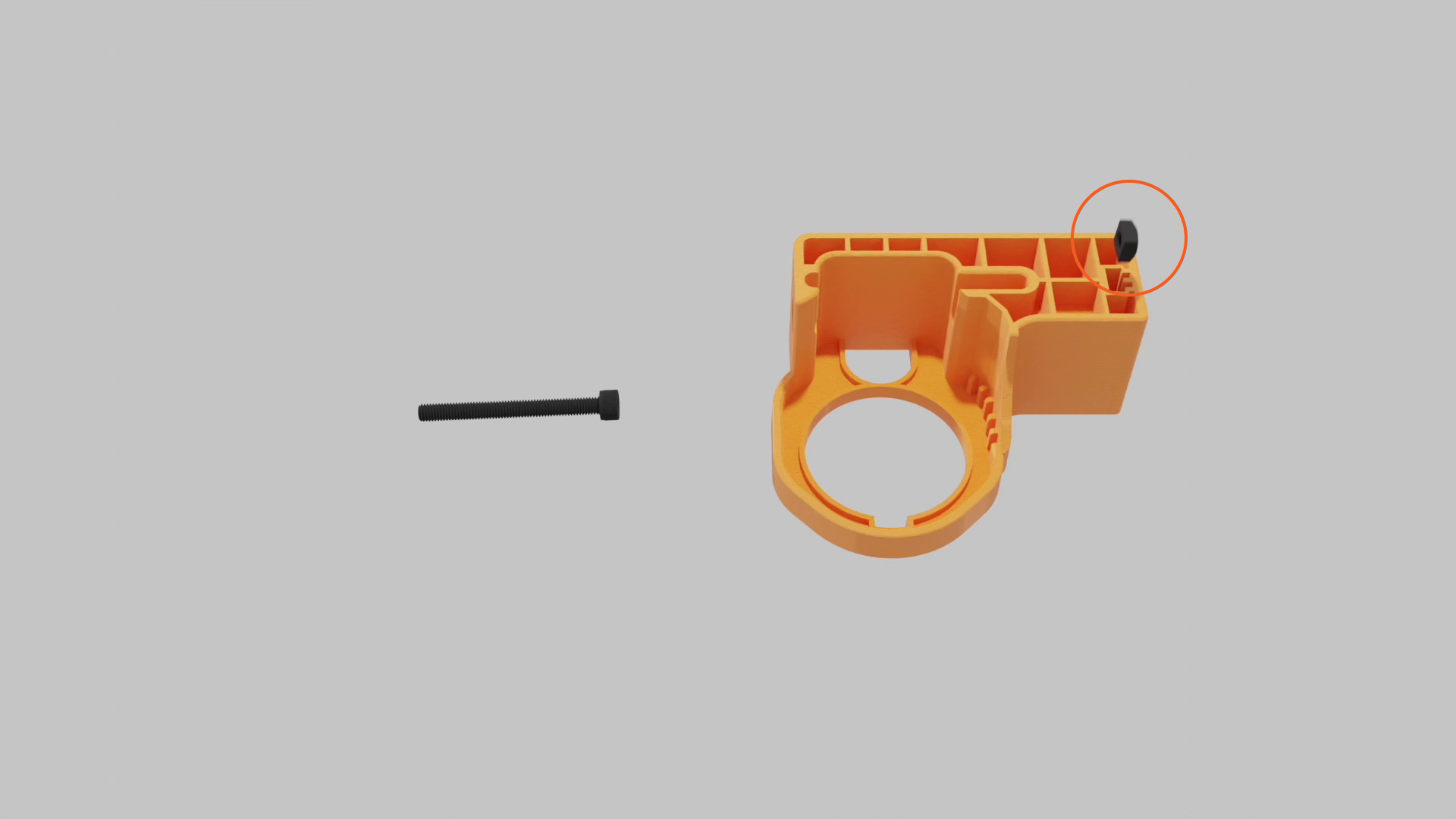
-
Insert the drive bolt from the side of the tool body and tighten.

-
Keep the guide pin and hex tool handy for future steps.
Identify Connector Type
Identify the connector type before beginning repairs.
Type A
-
Three oval shaped cutouts on the side of the connector
-
Silver latch pin
-
Replacement latch narrows at the tip and uses a longer silver-colored spring

Type B
-
No cutouts on the side
-
Black latch pin
-
Replacement latch stays wide at the tip and uses a shorter dark-colored spring

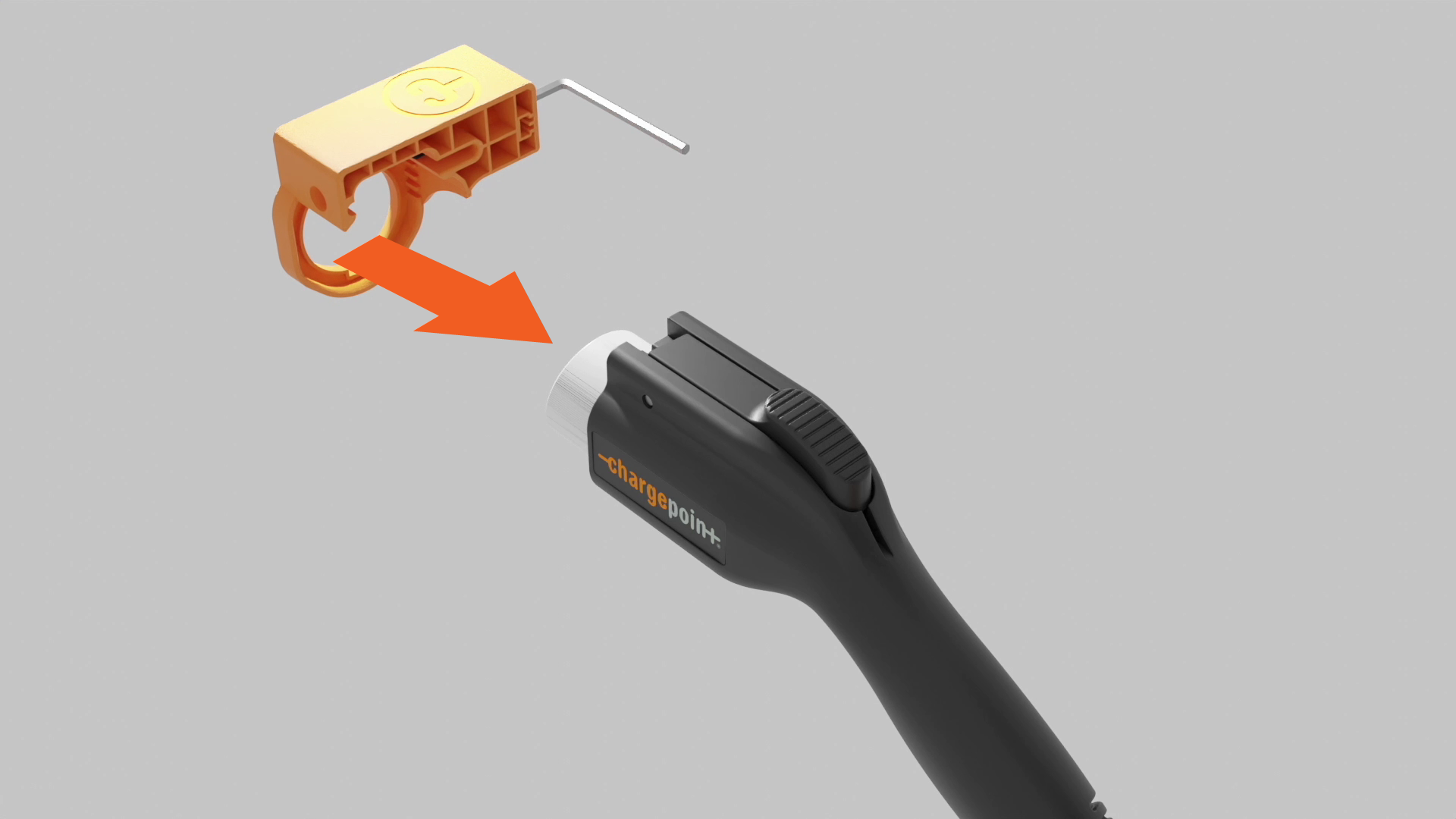
Repair Procedure
To repair, perform the following steps:
-
Use the hex wrench to loosen the drive bolt. Insert the guide pin into the pin slot.

-
Insert the J1772 connector into the repair tool, and push it into place until the latch pin aligns with the middle of the exit hole.

-
Use the hex wrench to tighten the drive bolt. The latch pin slowly extends from the exit hole. If you feel too much resistance but don't see the pin move, check the alignment and try again.

-
Tighten the drive bolt until the latch pin fully extends from the exit hole. Remove it by hand.
Keep the latch pin, you’ll need it later.
-
Loosen the drive bolt 5-10 revolutions and remove the connector from the tool.
-
Use the hex wrench to push the guide pin out.

-
Remove the broken latch and spring.

-
Install the spring by placing one end onto the plus-shaped indent of the replacement latch.

-
Gently align the other end of the spring with the circular indentation in the connector. Align the pin holes in the latch and connector.
If the spring is not set properly, it might pop out and get damaged when the latch is depressed.
-
Insert the guide pin into the latch to hold the pieces together. Squeeze the latch to ensure the spring functions correctly.

-
Use the hex wrench to loosen the drive bolt. Insert the latch pin fully into the pin slot.

-
Insert the J1772 connector into the repair. Press into place until the guide pin hole aligns with the exit hole.

-
Use the hex wrench to tighten the drive bolt. The guide pin slowly extends from the exit hole. If you feel too much resistance but don't see the pin move, check the alignment and try again.

-
Tighten the drive bolt until the guide pin fully extends from the exit hole. Remove the pin by hand.
Keep the guide pin so you can use the tool to repair another connector.

-
Loosen the drive bolt 5-10 revolutions, then remove the connector from the tool.

-
Insert the connector into the station holder. If it locks securely and charges a vehicle, the repair is complete.