Install the Reset Switch
Required Tools and Materials
|
|
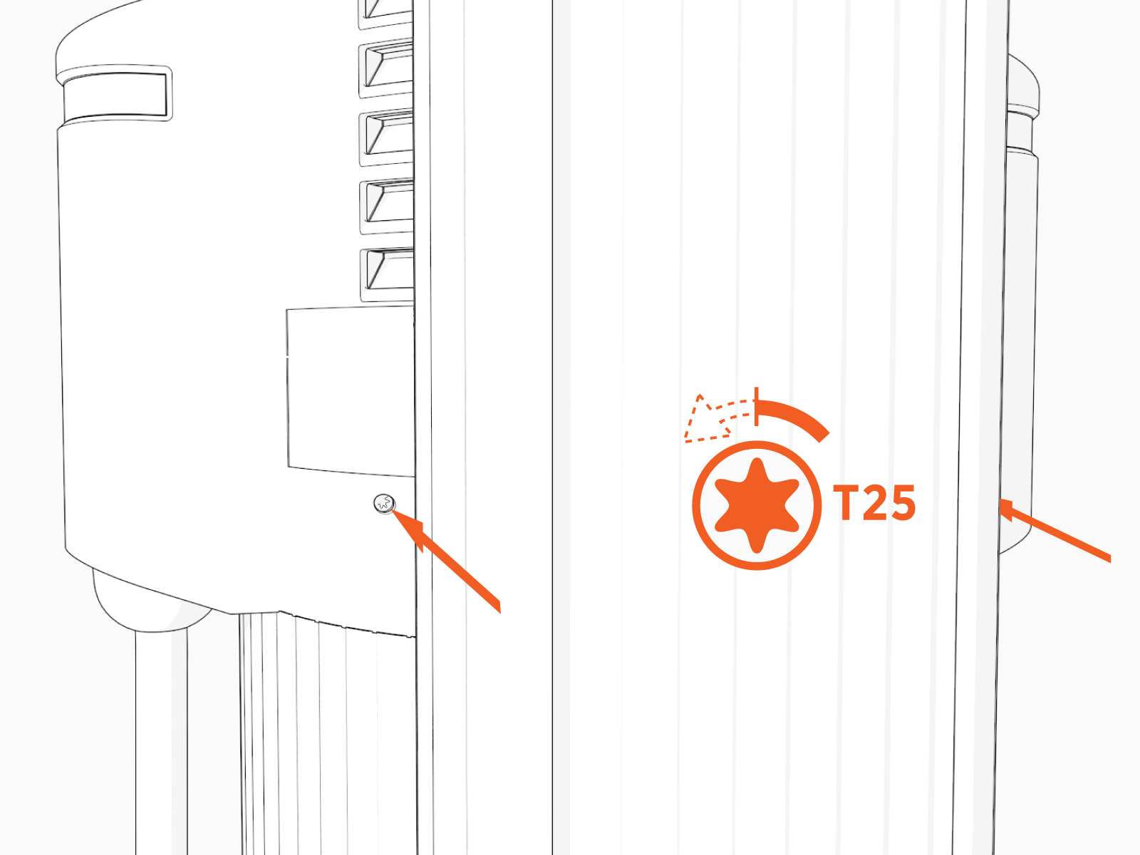
Torx screwdriver (T25) |
|
|
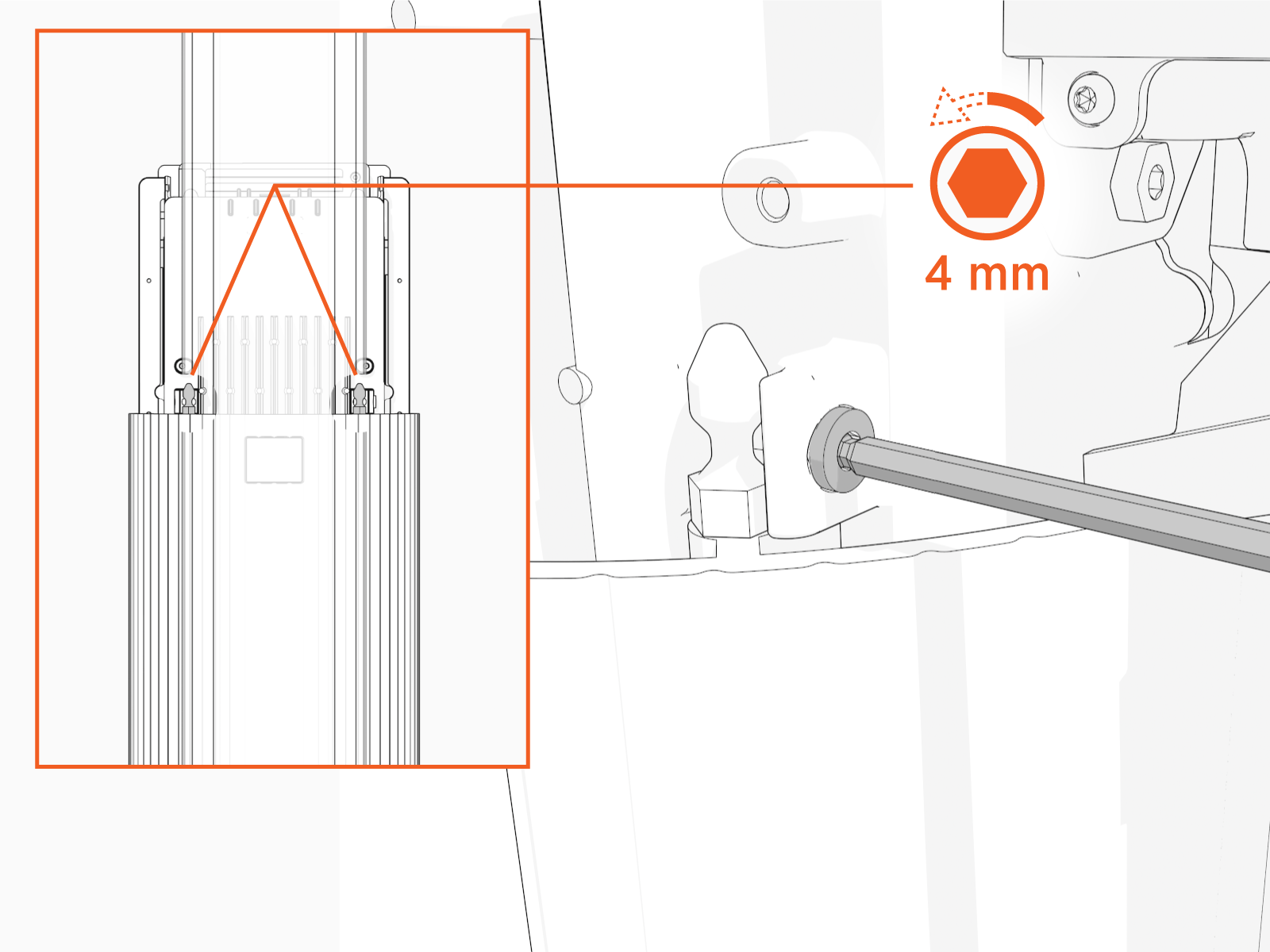
4 mm hex wrench |
|
|
Isopropyl wipes |
|
|
Paper towel roll |
Remove the Head Assembly
Perform the following steps to remove the head assembly:
-
Use your ChargePoint card or the mobile app to start a charging session, unlock the charging cables, and set them gently down.

-
Disconnect the power to the CP6000 at the service panel.
Risk of shock
-
Before any procedure, the technician must disconnect the power.
-
Follow local code to de-energize the applicable circuit and lock out/tag out the disconnect before proceeding. Use a multimeter to test that power is off.
-
Keep power off until the top cap is correctly reinstalled and the work is complete.
Failure to follow these instructions can result in serious injury, loss of life, or property damage.
-
-
Use the L-wrench to loosen the two T25 screws securing the top cap.
-
Remove the top cap.

-
Use the L-wrench to loosen, but do not remove, the screws securing the head assembly.
-
Lift the head assembly to remove it from the pedestal or wall mount enclosure. Place it gently face down on a padded surface.

-
Slide the cover up and remove the cover from the power plate.

Install the Reset Switch
Perform the following steps to install the reset switch:
-
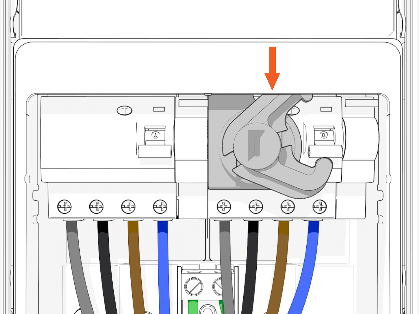
Clean the outer sides of the RCCB
 Residual Current Circuit Breaker terminal block with isopropyl wipes.
Dry the RCCB Residual Current Circuit Breaker terminal block with a paper towel or clean cloth.
Residual Current Circuit Breaker terminal block with isopropyl wipes.
Dry the RCCB Residual Current Circuit Breaker terminal block with a paper towel or clean cloth.

-
Remove the liner from reset switch to expose the adhesive.

-
Align the edge of the reset switch with the edge of the left side of the right most RCCB
Residual Current Circuit Breaker terminal block.
If you are using one of the station ports, affix the reset switch to the RCCB Residual Current Circuit Breaker terminal block on the right side.
 Ensure the reset switch clears the RCCB Residual Current Circuit Breaker reset button.

-
Affix the reset switch.
Press and hold switch in place for at least 30 seconds.
-
Repeat the previous steps to install the second reset switch. Install the second switch on both single and dual output stations.

-
Install the new power plate cover.

-
Align the rails on the head assembly with the pedestal and slide it part of the way into the pedestal housing.
Insert an L-wrench or a screwdriver through the hole on the side of the head assembly to hold the head assembly in the raised position.

-
Ensure everything is aligned before lowering the head assembly all the way down.
Avoid damaging cables when installing the head assembly. -
Remove the L wrench.
Slide the head assembly all the way into the pedestal housing. Ensure the head assembly is fully seated.

-
Using the L-wrench or 4 mm hex tool, tighten two screws.

-
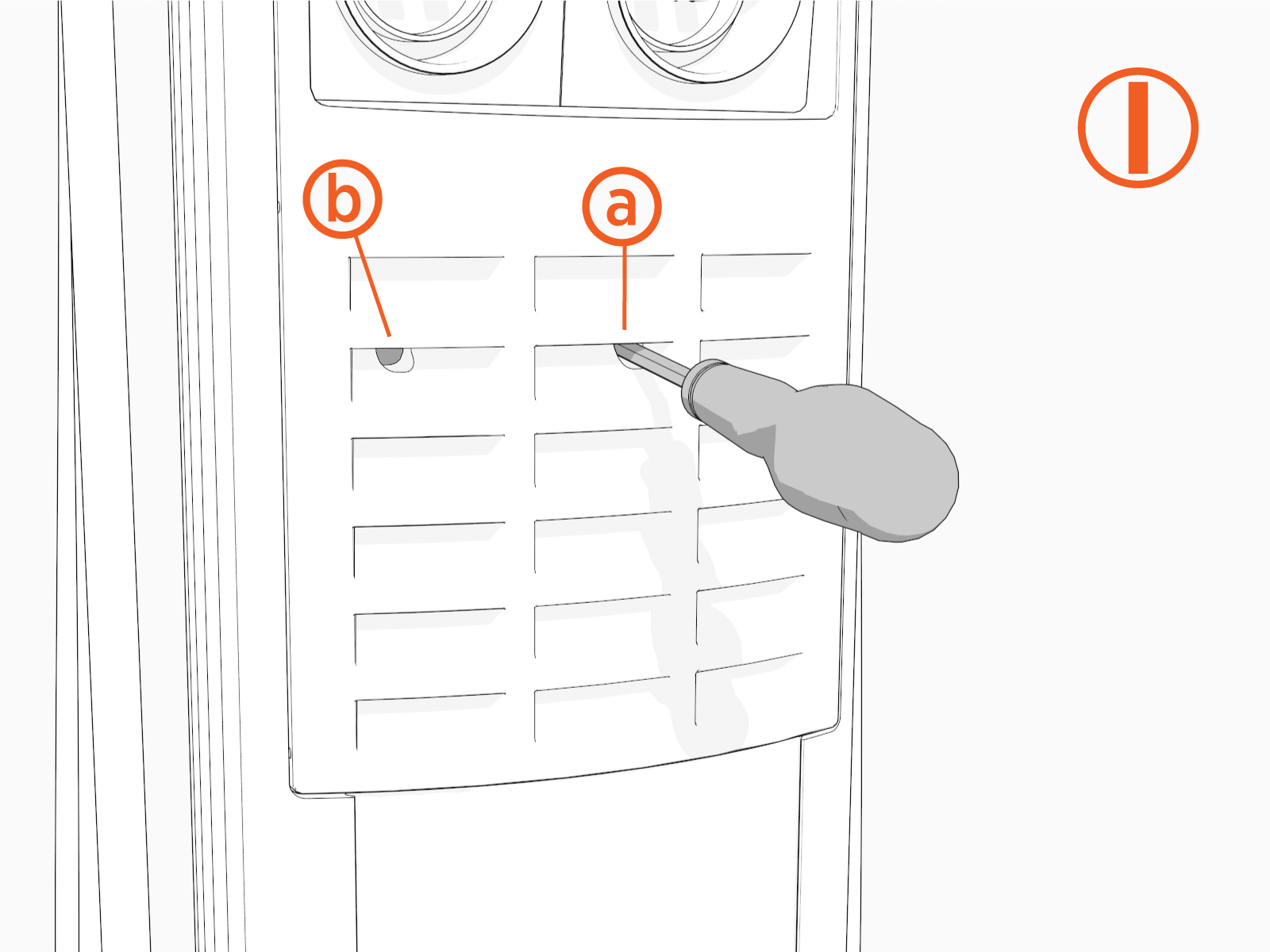
Gently insert an 8 mm flat blade screwdriver (a) through one of the two holes (b) in the front panel.
-
Insert the screwdriver (a) at an angle to access the right RCCB
Residual Current Circuit Breaker. 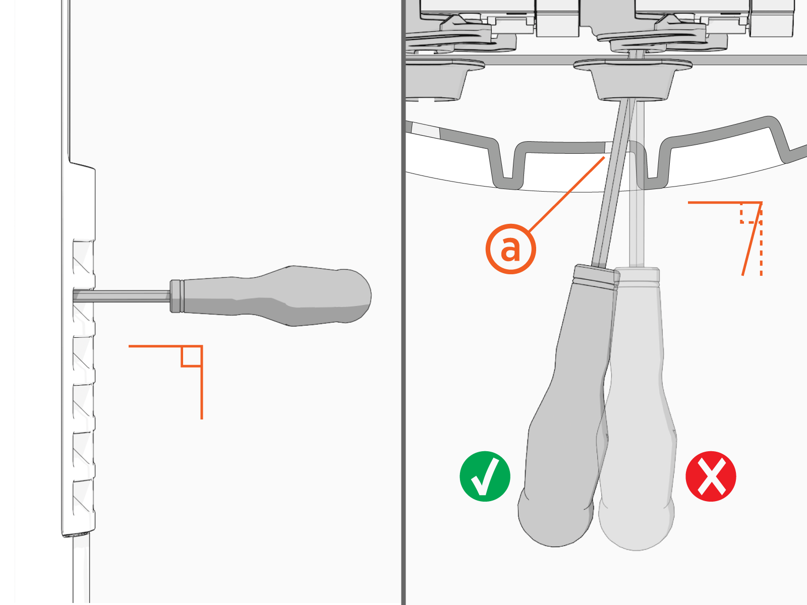
-
Use the screwdriver to turn the activator (c) clockwise to turn the RCCB
Residual Current Circuit Breaker (d) off.
-
Use the screwdriver to turn the activator counter-clockwise to turn the RCCB
Residual Current Circuit Breaker on again. The activator passes over the Test button (e) during this process. Red indicates the power is ON. Green indicates the power is OFF.
 -
If both ports are active, insert the screwdriver straight through the front panel (f) to access the left RCCB
Residual Current Circuit Breaker. 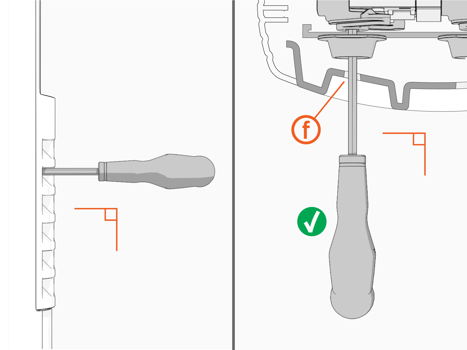
-
Slide the top cap onto the head assembly, adjusting as necessary to clear the charging cables, until it fits into place.

-
Torque two captive screws to 1.1 Nm (10 in-lb).

-
At the electrical panel, power up the station.
One or both port LEDs appear Red until the lockout faults are cleared.
Next Steps
Clear Lockout Faults
When you replace a part, the station triggers lockout faults.
To clear lockout faults, go to chargepoint.com/support and contact technical support using the appropriate region-specific number.
