DC Smart Cable
This section provides information on replacing a DC smart cable.
Required Tools and Materials
|
|
10 mm deep socket |
|
T25 security screwdriver |
|
|
Stepladder |
|
Removable zip ties |
Before You Begin
-
Power off the charging station.
-
Determine if the Power Link 1000 has preassembled covers or unassembled components, remove them as necessary.
-
Remove top access panel.
-
Position a stepladder so you can reach the top access panel.
-
Loosen captive screws and lift off the panel.

AFTER REPLACING, REVERSE THE ABOVE STEPS TO COMPLETE THE SERVICE.
Replace DC Charging Cable
To replace the DC charging cablem complete the following steps:
Release Cable
-
Loosen the tetherball screw (if present).
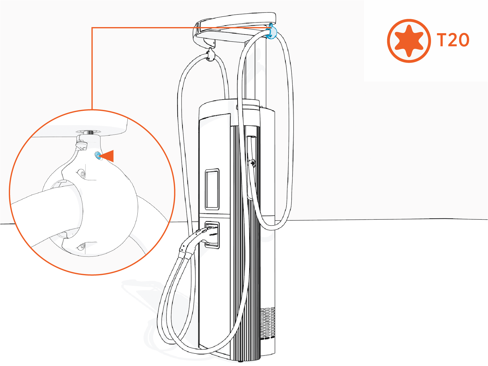
Torque to 2.8 Nm (25 in-lb).
-
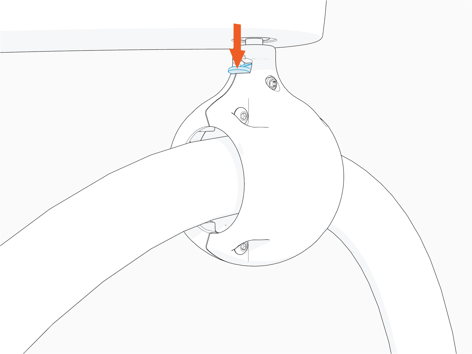
Hold the tetherball and gently push it up to unlatch the spring. The spring tab flips downward.
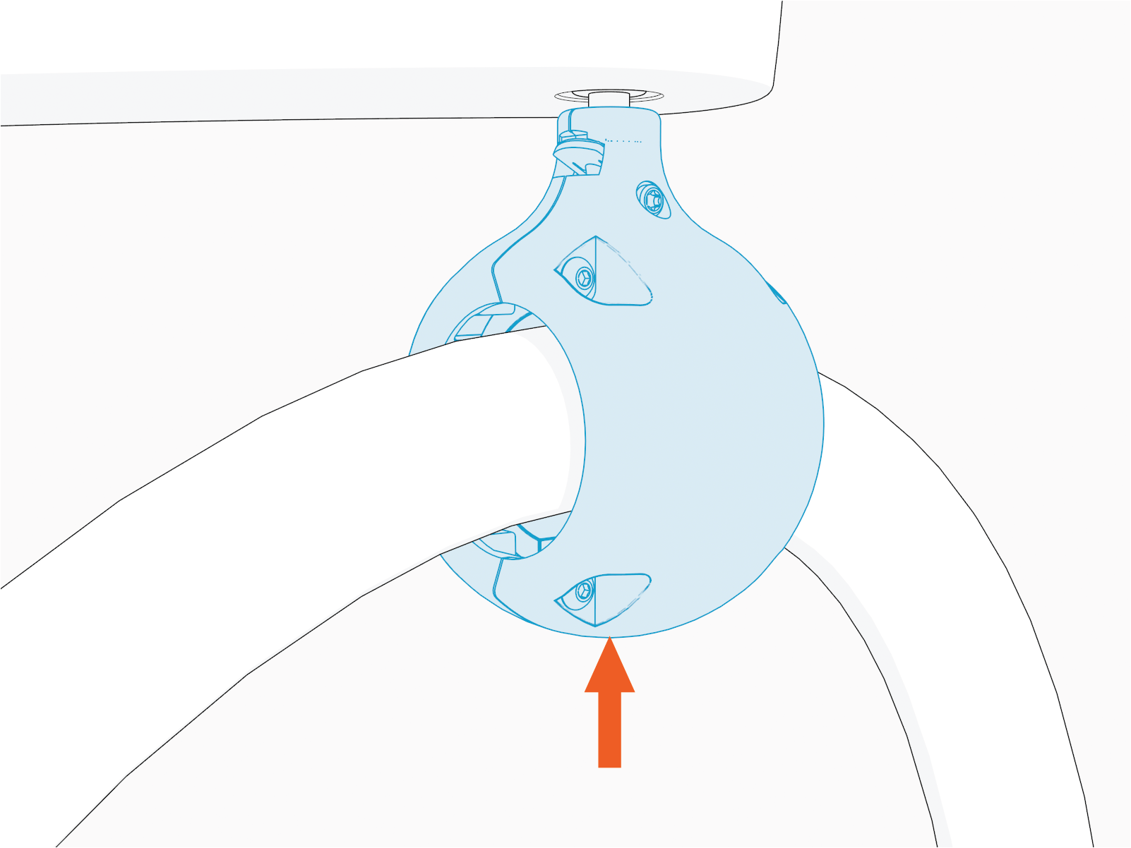
-
Hold down the spring tab.
-
Remove tetherball from the tether pin to release the cable.
Place the cable on a padded surface to avoid scratches on the cable's surface.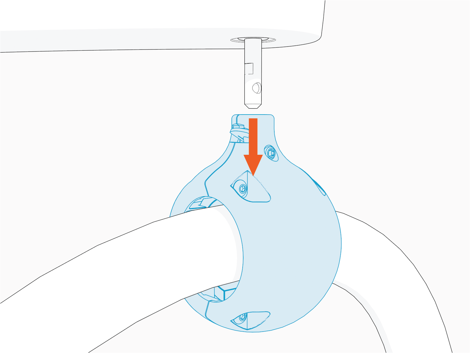 Align the spring with flat notch on the tether pin and gently push the tetherball onto the pin to suspend the cable as shown in the image below.
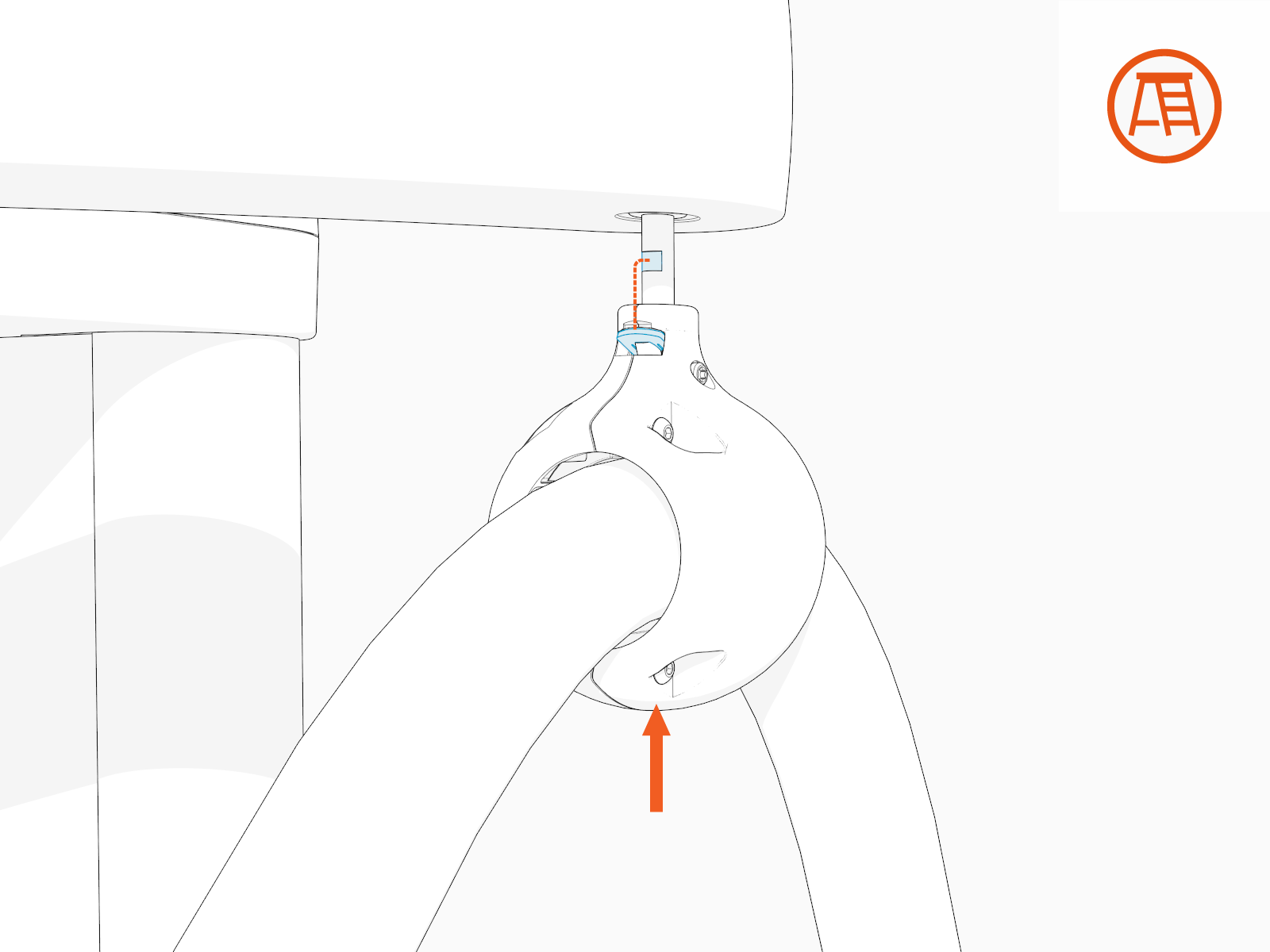
Remove Charging Cable
-
Disconnect these for each charging cable.
-
One Ethernet connector (left or right, RJ45 connector plugged into RJ45 coupler from the contactor box).
-
One 48 V connector (left or right, near opening where charging cable enters cabinet).
-
One ground wire (inside the cabinet near the cable housing). Uninstall the M6 nut.
-
DC high-voltage cable lugs (left or right, front of contactor box).
-
- Take a photo to refer to when you reinstall.
- If you don't reinstall lugs to their original plate locations, you could reverse positive (red) / negative (black) polarity. This could damage the charging station or vehicle.
- If you switch connector ports, you could disrupt status reporting between the local system and the ChargePoint Platform or cause charging cable misidentification.
Loosen the M5 screws (x4) (use T25 security screwdriver) on the cable housing.

Hold the cable housing in one hand and route the connectors, DC cables and lugs, ferrite ring, and ground wire out of the cabinet.
Install Replacement Charging Cable
To install the replacement charging cable, complete the following steps:
Route Into Cabinet
Unwrap the charging cable.
Do not unwrap the cable handle to prevent it from getting scratched during the install process.
Route the connectors, DC smart cables and lugs, ferrite ring, and ground wire into the upper cabinet through the opening behind the cable housing.

Tilt the ferrite ring to fit.
If you removed the zip tie, attach a removable zip tie to the cables and ferrite ring.

Cable Housing
Align the cable housing onto the pegs. Torque to 4.5 Nm (40 in-lb).
Hold or clamp the cable housing in position.

Ground Wire, 48 V Power, and Ethernet
Locate the bolt near the cable housing. Install two ground wires for each charging cable. Secure the wires with a nut. Torque to 5.6 Nm (50 in-lb).


Locate the right and left wire harness. Connect one 48 V four-pin power connector to each.

Refer to the photos taken when disconnecting the original charging cables. For the remaining steps, attach the same connector to the same port and the same lug to the same plate for each replacement charging cable.
- If you switch connector ports, you could cause charging cable misidentification or disrupt status reporting between the local system and the ChargePoint Platform.
- If you don't attach the lugs to their correct plate locations, you could reverse positive (red) and negative (black) polarity. This could damage the station or vehicle.
Plug the RJ45 Ethernet connectors from the left and right charging cables into RJ45 couplers on the left and right side respectively.

Refer to the photo you took.
DC Lugs and Nuts
Land each positive and negative DC lug with a nut on the correct plate.
Refer to the photo you took.
Torque to 5.6 Nm (50 in-lb).
Ensure that the cable pigtails (i.e., loose ends) crimped into a lug are not rubbing against the lug landing plate.
Install either four DC lugs for each charging cable of 350 A or two DC lugs for each charging cable of 250 A or less.
350 A:

250 A or less:

You must install the charging cable lug to either a left or right plate corresponding to the left or right charging cable.
Left and Right Charging Cables

Left charging cable
Right charging cable
Red DC Cables to Positive Connectors

You must install each charging cable lug to either an upper or a lower plate to maintain the correct negative (black) or positive (red) polarity.
- CHAdeMO has white and black color codes whereas NACS
 North American Charging Standard, CCS1, and CCS2 have red and black color codes.
- It is easiest to unfasten all cables for better access, even if only one cable is being replaced.
If you don't install lugs to the correct plate locations, you could reverse positive (red) / negative (black) polarity. This could damage the station or vehicle.
Hang the Charging Cable
Position the stepladder so that you can reach the hanging point.

Ensure the screw (if present) on the charging cable tetherball is loose.
 on the charging cable tetherball is loose.")
Align the spring with flat notch on the tether pin and gently push the tetherball onto the pin to hang the cable.
If necessary, slide the tetherball to a position on the cable such that the cable doesn't touch the ground when installed onto the CMK
Cable Management Kit tether pin.
Torque the screw to 2.8 Nm (25 in-lb)
.")
- To adhere to ChargePoint best practices, complete the post-service checklist before you leave the site.
For assistance or to return a faulty part to ChargePoint, go to chargepoint.com/support and contact technical support using the appropriate region-specific number.
