Contactor Box
This section provides information on replacing the contactor box.
Required Tools and Materials
|
|
T25 security screwdriver |
|
Stepladder |
Before You Begin
-
Power off the charging station.
-
Determine if the Power Link 1000 has preassembled covers or unassembled components, remove them as necessary.
-
Remove the DC smart cable bus bar safety cover and L shaped bus bar safety cover.
-
Remove top access panel.
-
Position a stepladder so you can reach the top access panel.
-
Loosen captive screws and lift off the panel.

AFTER REPLACING, REVERSE THE ABOVE STEPS TO COMPLETE THE SERVICE.
Replace the Contactor Box
To remove the contactor box, complete the following steps:
-
Disconnect the following connectors from the contactor box:
(a) SSLAN
 Smart Switch Local Area Network power connectors
(b) 6-pin ISOMON
Isolation Monitor power connector(c) 10-pin CAN connector
(d) Ethernet connector
(e) 3-pin nano-fit connector
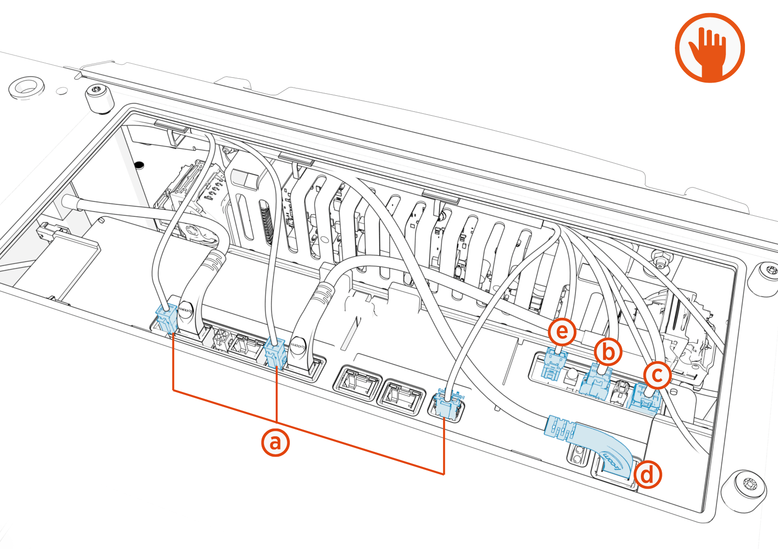
When installing the replacement FRU
Field Replaceable Unit, refer to Contactor Box Wiring for wire installation details. -
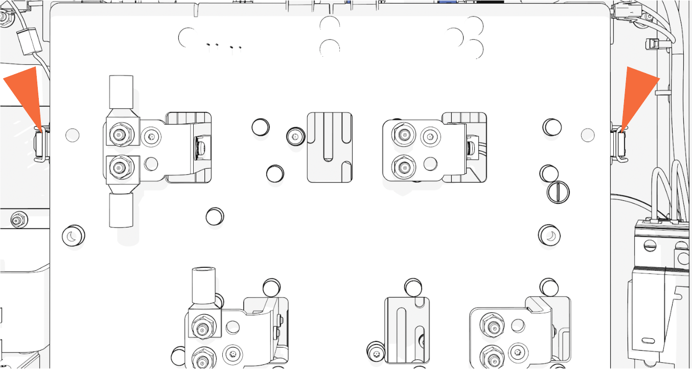
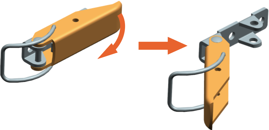
Unlatch the contactor box.
-
Locate the two latches on the left and right side.
-
Pull the lever on each to unlatch the contactor box.
-
-
Hold both sides and pull the contactor box out.
Use more force on the lower part of the contactor box to release that area from the bus bar clips.HeavyMaintain a secure hold of this heavy part.
If you do not, you could drop this item and damage it or injure yourself or others.
Reverse the above steps to reinstall with replacement FRU![]() Field Replaceable Unit.
Field Replaceable Unit.
Contactor Box Wiring
To rewire the contractor box, complete the following steps:
-
Connect the 3-pin nano-fit connector.

-
Connect the Ethernet connector (for the CCOM
Control and Communications Module).
-
Connect the 10-pin CAN connector (for the CCOM
Control and Communications Module).
-
Connect the 6-pin ISOMON
Isolation Monitor power connector.
-
Connect the SSLAN
Smart Switch Local Area Network power connectors.
- To adhere to ChargePoint best practices, complete the post-service checklist before you leave the site.
-
For assistance or to return a faulty part to ChargePoint, go to chargepoint.com/support and contact technical support using the appropriate region-specific number.
