Covers and Panels
This section provides instructions for removing and replacing covers and panels in the Power Link 2000.
Required Tools and Materials
|
|
Stepladder |
|
Cut-resistant gloves |
|
|
T25 Security screwdriver, for: |
|
T10 Torx screwdriver (for upper and lower cover trims) |
|
|
10 mm hex wrench (for doors) |
|
Isopropyl pads (for upper and lower cover vinyls; required only if applying new vinyls) |
|
|
Vinyl application tool (for upper and lower cover vinyls); required only if applying new vinyls) |
|
|
Before You Begin
Before beginning work, complete the following steps:
-
Refer to the site drawings and identify the charging stations to be serviced.
-
End all charging sessions and activity for the stations to be serviced.
-
Use the following sequence to remove a cover:
-
-
Removing (b) lets you open the lower door and it can be removed without removing (a).
-
Removing (a), (b), and (c) lets you open both lower and upper door.
-
-
-

-
-
If you want to replace ChargePoint branded vinyls with custom branded vinyls, refer to these instructions.
After replacing the components, reverse the above steps to complete the service.
- To adhere to ChargePoint best practices, complete the post-service checklist before you leave the site.
For assistance or to return a faulty part to ChargePoint, go to chargepoint.com/support and contact technical support using the appropriate region-specific number.
Replace the Top Cap
To replace the top cap, complete the steps given below.
Remove the Cap
Loosen the screws (x4, two at front and two at rear).
.")
Lift the top cap.

Reinstall the Cap
Align the screws (x4) and install the top cap.
Front screws (x2)
 to install the top cap.")
Rear screws (x2)
 to install the top cap.")
Make sure that the top cap sides are seated on edges on top of the side panels (x2).
.")
Torque the rear screws (x2) to 2.8 Nm (25 in-lb) and front screws (x2) to 1.7 Nm (15 in-lb).
 to 2.8 Nm (25 in-lb) and front screws (x2) to 1.7 Nm (15 in-lb).")
Replace the Front Lower Cover
To replace the front lower cover, complete the steps given below.
Remove the Cover
Remove charging cable connectors from the holster.
Pull the cover up by holding upper side of the holster trim.

Flex any one side of the cover to remove the corresponding edge out of the groove on the side panel.

Remove the other side edge out of the groove on the other side panel.
Reinstall the Cover
Align top edge of the lower cover with the lower edge of the Control and Communication Module (CCOM
 Control and Communications Module) trim.
While overlapped with the upper cover, insert any one side of the cover into the groove on the side panel.

Gently flex the cover to insert its other side into the groove on the other side panel. Make sure that the top and bottom corners of the cover are seated in the groove.

Press in below the holster trim and lower side of the cover; while pressed in, slide the cover down to engage the hooks (x2) behind the cover. See the previous step for the exact location of the hooks.
 behind the cover. See the previous step for the exact location of the hooks.")
Make sure that the lower edge of the holster bracket and holster trim are aligned.

Place charging cable connectors into the holsters.

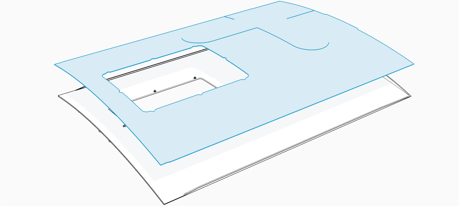
Replace the Front Upper Cover
To replace the front upper cover, complete the steps given below.
Remove the Cover
Remove top cap.
Remove front lower over.
Hold and flex lower side of the cover outward to disengage the ball studs (x3) hooked to the bracket on the upper door.
 hooked to the bracket on the upper door.")
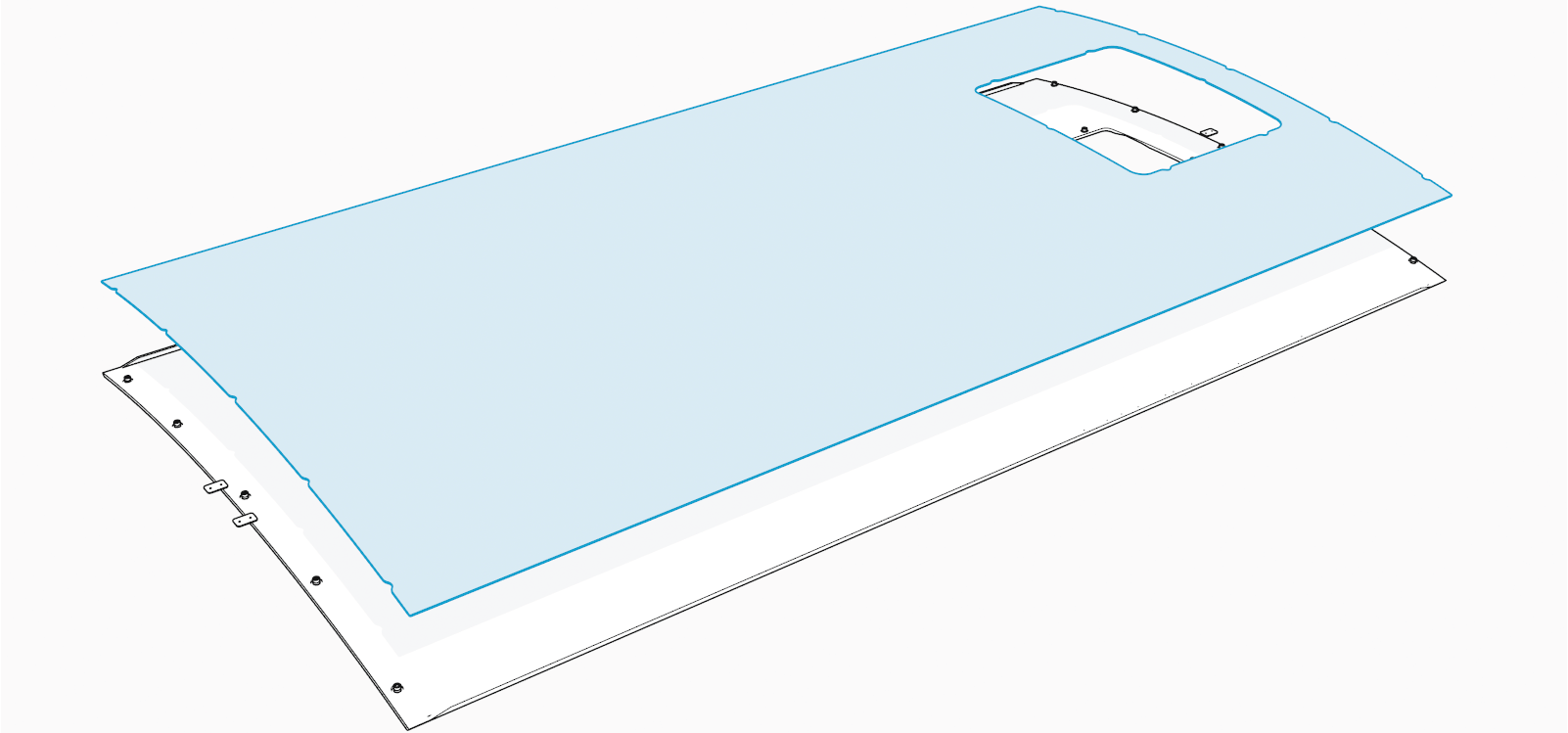
Flex any one side of the cover to remove the corresponding edge out of the groove on the side panel.

Remove the other side edge out of the groove on the other side panel.
Reinstall the Cover
Insert any one side of the cover into the groove on the side panel.

Gently flex the cover to insert its other side into the groove on the other side panel. At the same time, align and hook the ball studs (x3) behind the cover into the holes (x3) in a bracket on the upper door.
 behind the cover into the holes (x3) in a bracket on the upper door.")
Alternatively, you can hold and flex the lower side of the cover slightly outward. While flexed, align the ball studs (x3) behind the cover with the holes (x3) in the bracket on the upper door and press in.
 behind the cover with the holes (x3) in the bracket on the upper door and press in.")
Make sure that the screws (x2) on the front upper cover are seated in their slots in the area light housing.
 on the front upper cover are seating in their slots in the area light housing.")
Reinstall front lower cover.
Reinstall top cap.
Replace the Cable Cap
To replace the cable cap, complete the following steps:
Remove top cap.
Determine which cable cap you want to remove (the one on the left side lets you remove the left side charging cable and the one on the right side lets you remove the right side charging cable).
Pull the cable cap up to remove and keep it aside to reinstall it later.

Reverse the above steps to reinstall the cable cap.
Replace the Side Panel
This section provides instructions for replacing a side panel. Before you start, determine which side panel you want to remove (left side panel or right side panel).
Remove the Panel
Remove these:
Open lower door.
If applicable, remove the lower bus bar safety cover.
Loosen the screws (x2).
.")
Slowly push upper side of the side panel up to disengage it from hooks (x2) on the frame.
 on the frame.")
Hold the charging cable up and out of the way to slowly lower and remove the side panel.
Remove the side panel and keep it aside to reinstall it later.

Reinstall the Panel
Hold the charging cable up and place it into the cable way on the side panel.

Align and install the side panel onto the hooks (x2) and alignment pins (x2) on the frame.
 and alignment pins (x2) on the frame.")
Slowly slide the side panel down to engage the hooks (x2) on the frame.
 on the frame.")
Align the screw holes (x2) on the rear side of the side panel with the screws (x2) inside the lower enclosure and torque them to 4.5 Nm (40 in-lb).
 behind the side panel with the screws (x2) inside the lower enclosure and torque them to 4.5 Nm (40 in-lb).")
If applicable, reinstall the lower bus bar safety cover.
Close lower door.
Reinstall cable cap.
Reinstall top cap.
Replace the Rear Upper Cover (LCC)
This section provides instructions for replacing the rear upper cover, specifically for Power Link 2000 with liquid cooled cable (LCC![]() Liquid Cooled Cable). To replace the rear upper cover, complete the following steps:
Liquid Cooled Cable). To replace the rear upper cover, complete the following steps:
Remove side panel.
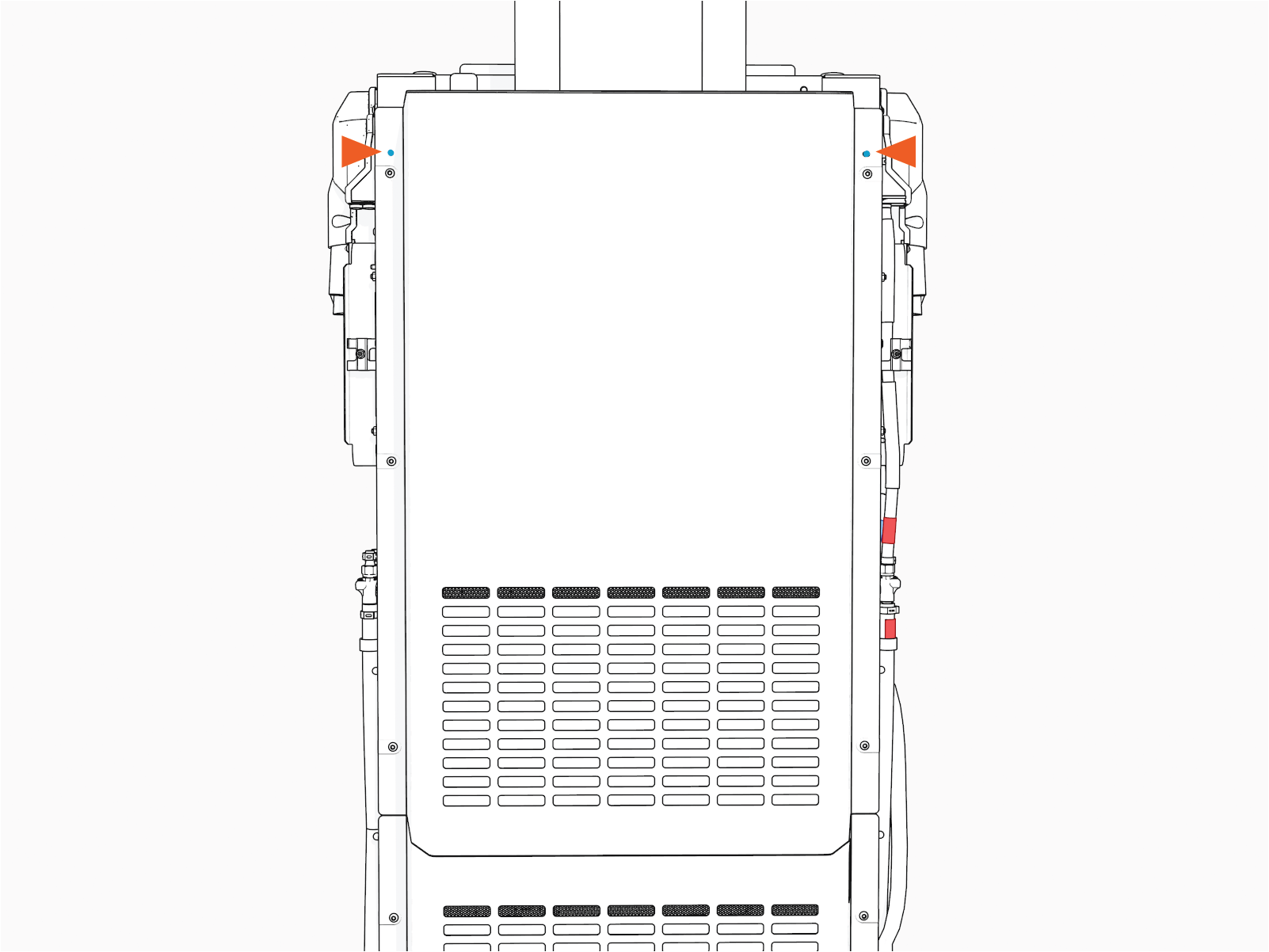
Loosen the screws (x6) to remove the cover.
 to remove the cover.")
Torque these screws to 4.5 Nm (40 in-lb).
If the rear upper cover has a card reader installed on it, disconnect the card reader cable before you remove the cover. Press the latch and pull the connector to disconnect the cable.

To reconnect, plug in. The connector latch must snap onto the receptacle with a click sound to ensure that the connection is secure.
Reverse the above steps to reinstall the rear upper cover.
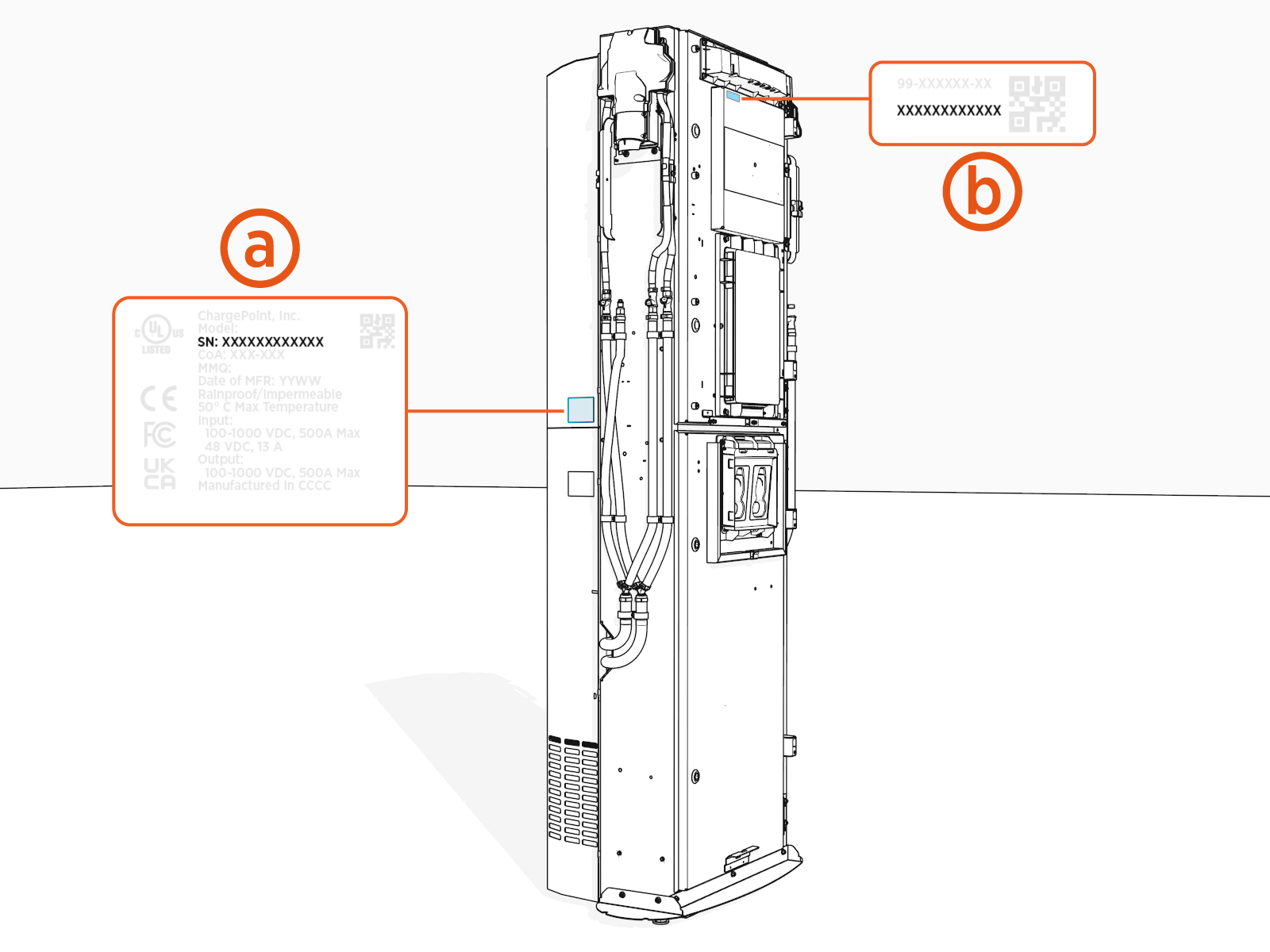
Label with SN on upper rear cover
Label with SN on station
Replace the Rear Lower Cover (LCC)
This section provides instructions for replacing the rear lower cover specifically for Power Link 2000 with liquid cooled cable (LCC![]() Liquid Cooled Cable). To replace the rear lower cover, complete the following steps:
Liquid Cooled Cable). To replace the rear lower cover, complete the following steps:
Remove these:
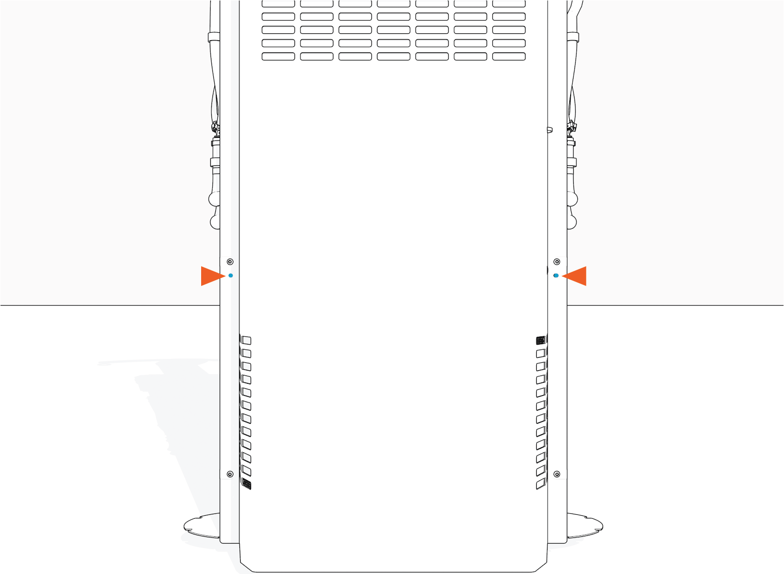
Loosen the screws (x6).
Torque these screws to 4.5 Nm (40 in-lb).
.")
Reverse the above steps to reinstall the rear lower cover.
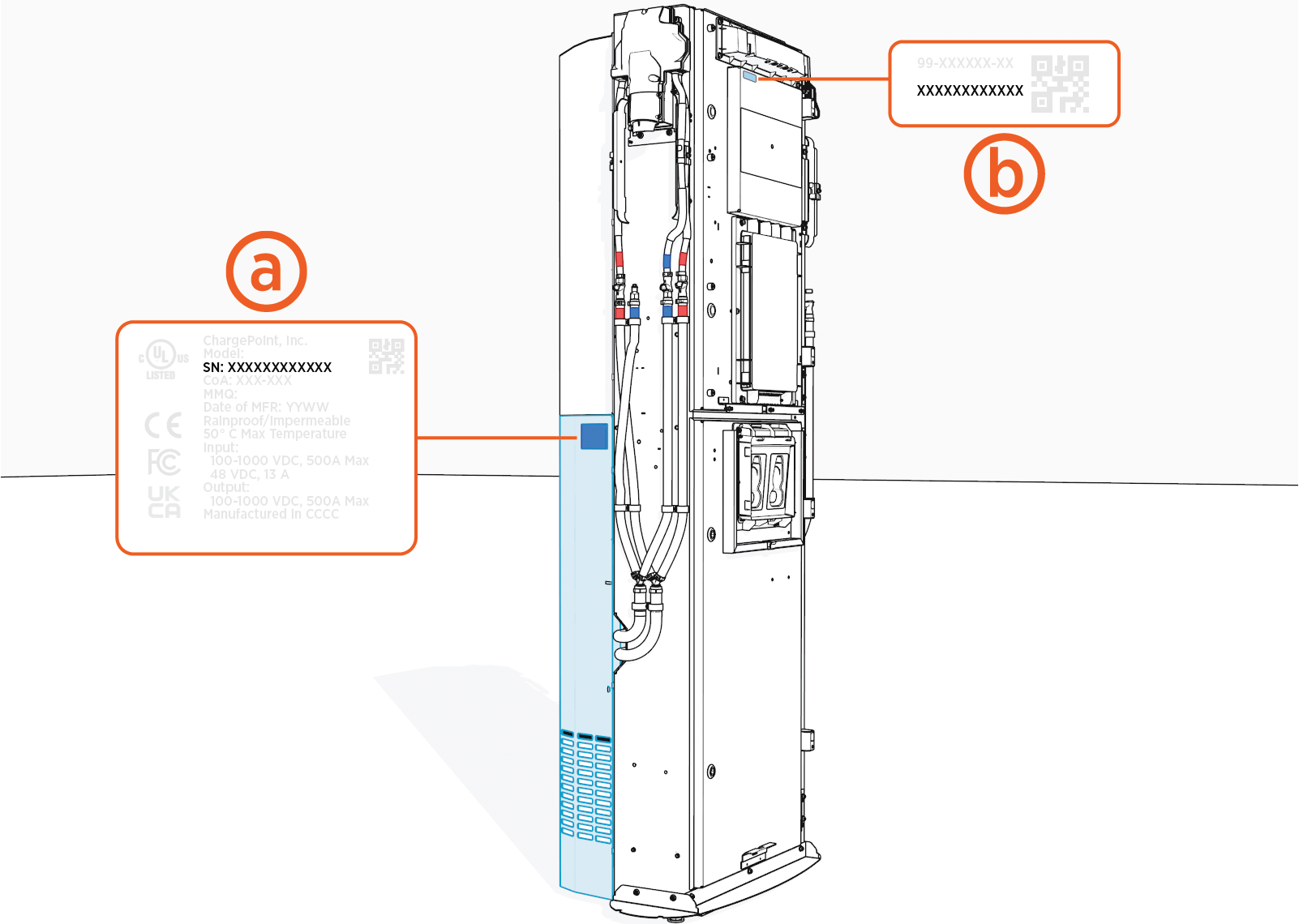
Label with SN on lower rear cover
Label with SN on station
Replace the Heat Sink Cap (LCC)
This section provides instructions for replacing the heat sink cap, specifically for Power Link 2000 with a liquid cooled cable (LCC![]() Liquid Cooled Cable). To replace the heat sink cap, complete the following steps:
Liquid Cooled Cable). To replace the heat sink cap, complete the following steps:
Remove top cap.
Loosen the screws (x2).
.")
Torque these screws to 4.5 Nm (40 in-lb).
Reverse the above steps to reinstall the heat sink cap.
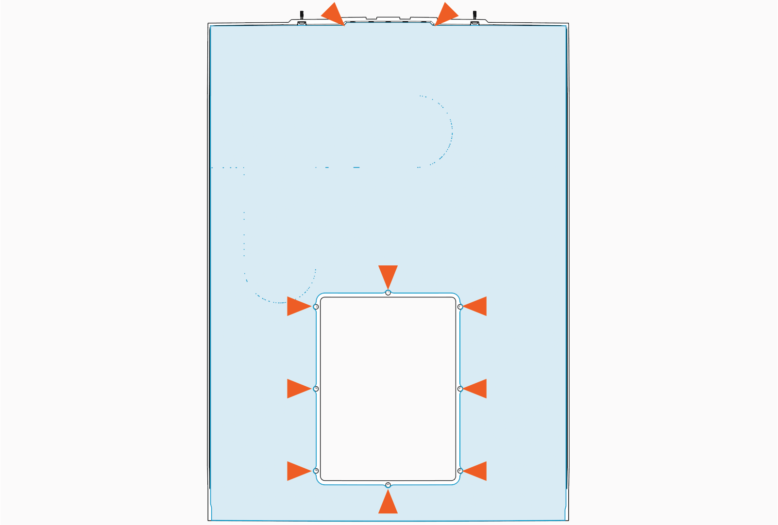
Replace the ChargePoint Vinyls with Custom Branded Vinyls
To replace ChargePoint vinyls with custom branded vinyls, complete the following steps:
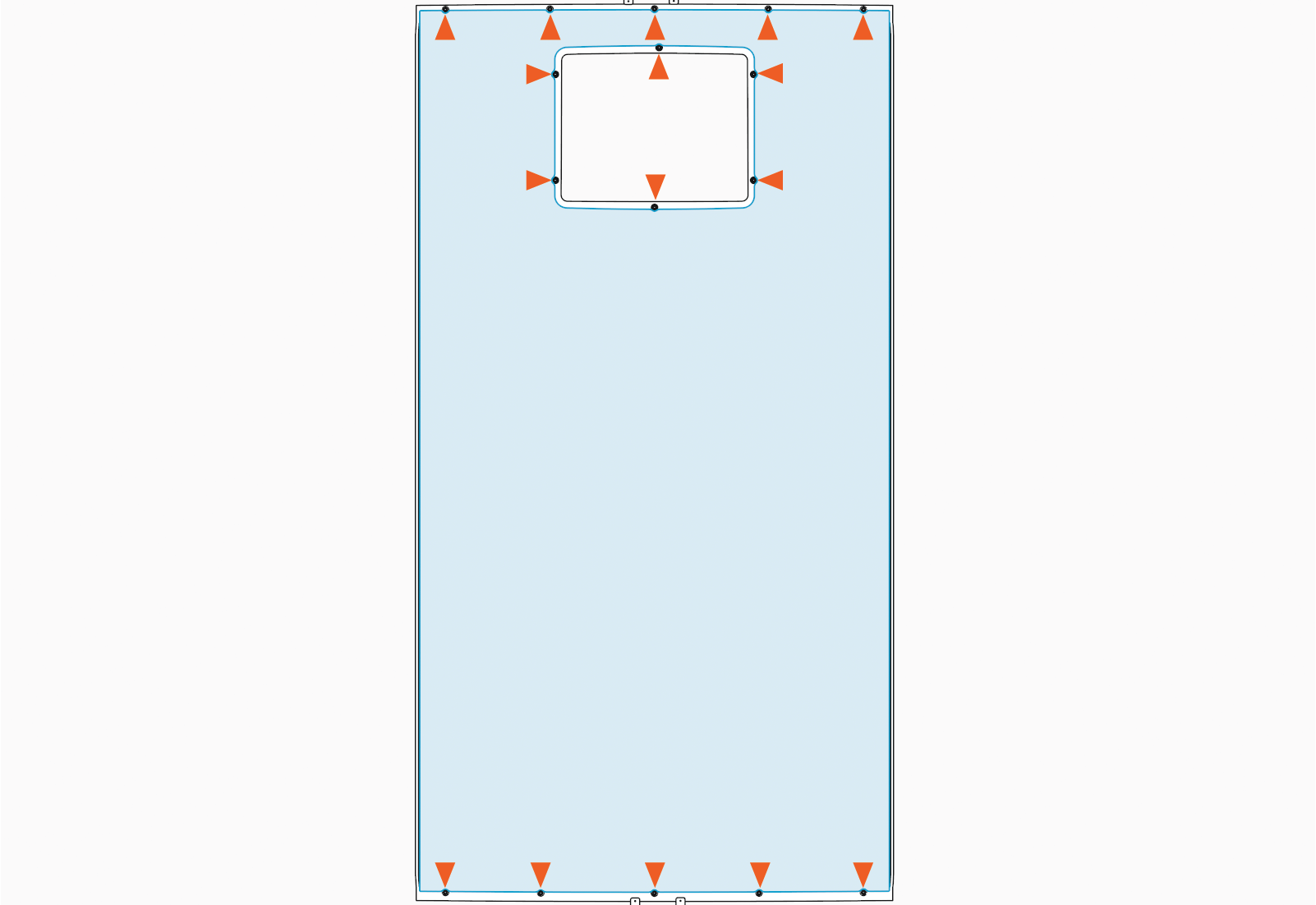
Remove the trims (x4) on the upper and lower covers.
Remove the screws (x24).
Upper cover screws (x8)
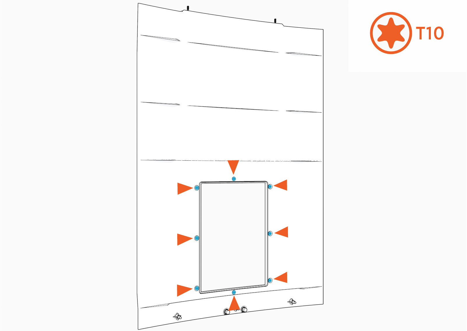
Lower cover screws (x16)
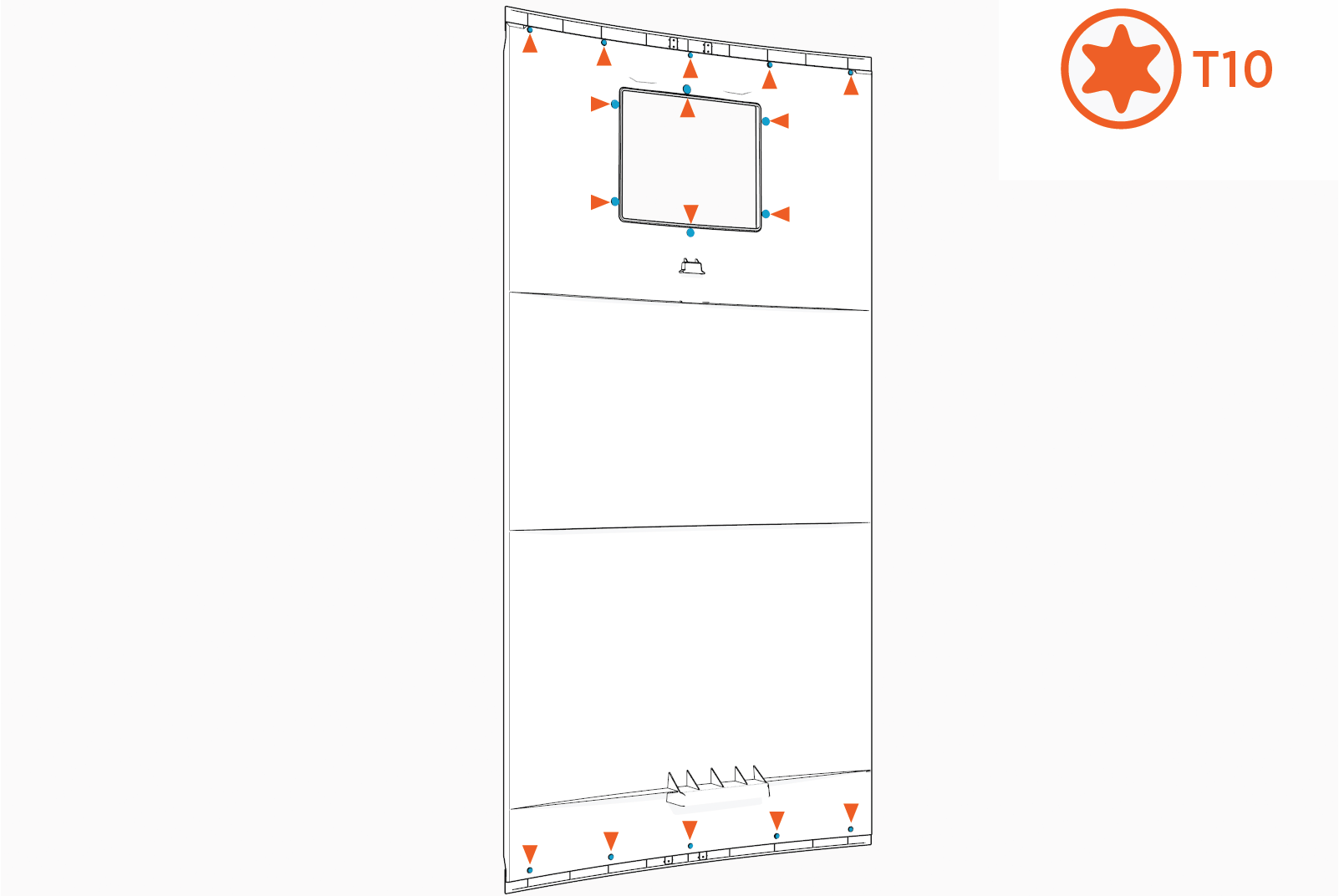
Torque these screws to 0.57 Nm (5 in-lb).
Remove the trims (x4) and keep them aside to reinstall later.
Upper cover trim
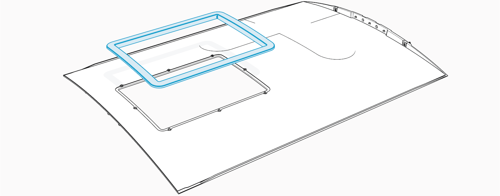
Lower cover trims (x3)
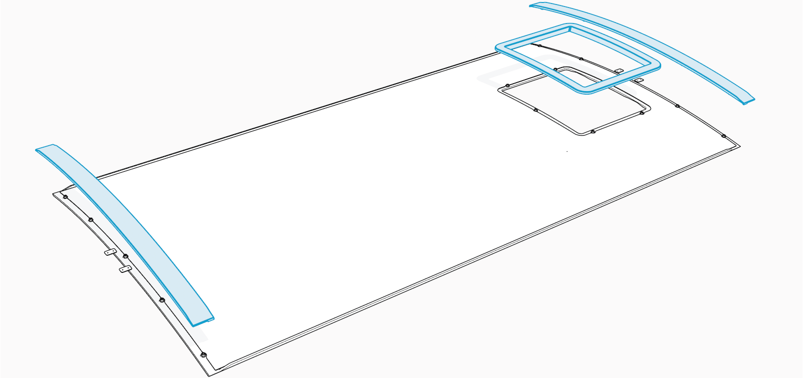
Peel off the ChargePoint branded vinyls.
Upper cover vinyl
Lower cover vinyl
Use an isopropyl pad to clean the adhesive residue and dust off the cover surfaces.
Affix the new custom branded vinyls.
Avoid scratching and stretching the vinyls while laying them.Remove the adhesive strip from the middle of the vinyl's back.
Use the screw and trim cutouts in the middle of the vinyl to align it with the cover.
Cutouts on upper cover vinyl (x10)
Cutouts on lower cover vinyl (x16)
Once aligned, gently press down on the adhesive surface to attach it to the cover.
Once the middle of the vinyl is attached, remove the adhesive strip on the left or right side of the vinyl.
Align the vinyl's edges with the cover and check for creases before attaching the adhesive surface to the cover. Repeat for the adhesive strip on the other side.
Reinstall the trims (x4) onto the upper and lower covers.
Open and Close the Doors
To open and close upper and lower enclosure doors, follow the steps given below.
Open the Doors
If you want to access a component in the upper or lower enclosure, power off before you open the upper and/or lower door.
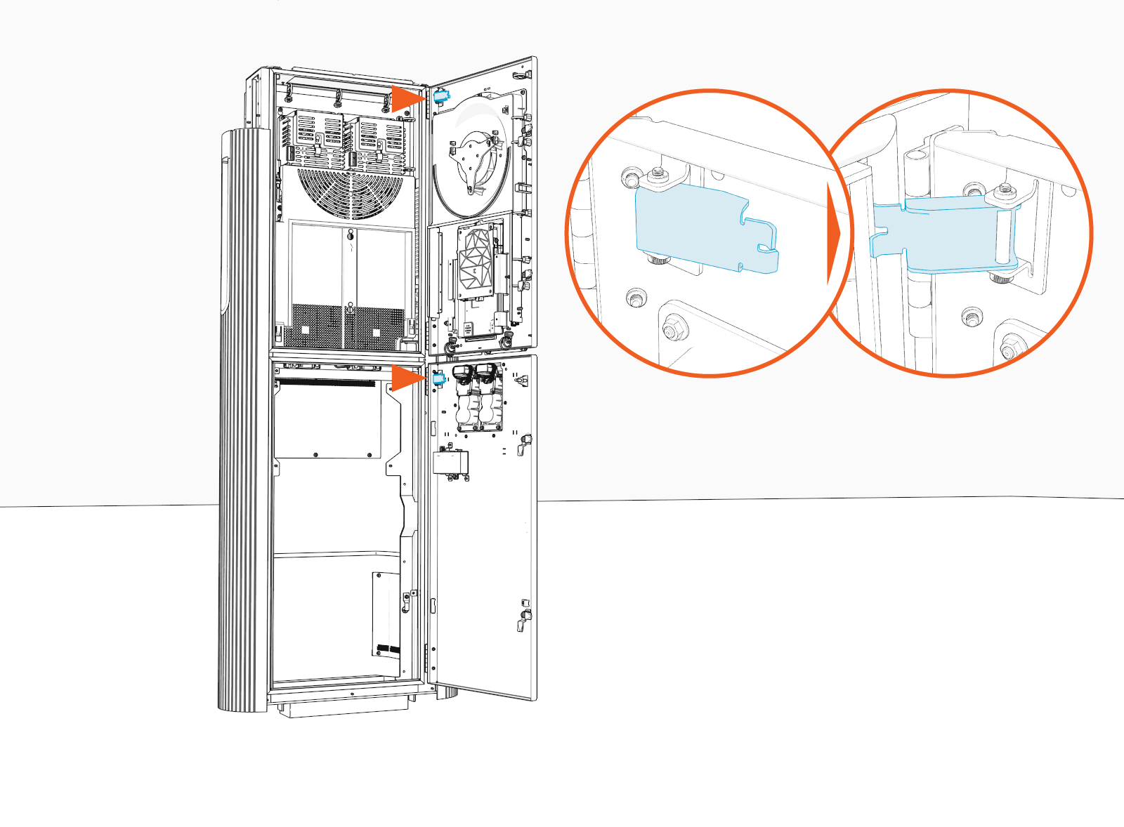
Quarter turn the door latches (x2 per upper and lower enclosure door).
The latch rotation direction shown in the illustration applies to Variation B Power Link 2000 units. For Variation A units, rotate each latch 90° clockwise to unlock the door. Refer to Appendix A: Variation Identification for further information.
.")
Open the door and engage the door stopper (x1 per upper and lower enclosure door).
Close the Doors
Check the 48 V DC circuit breakers to ensure they are in the ON position before you close the upper door. The location of the breakers depends on the Power Link 2000 variation.
Variation A Power Link 2000 Variation B Power Link 2000  up to turn the LV power supply on.")
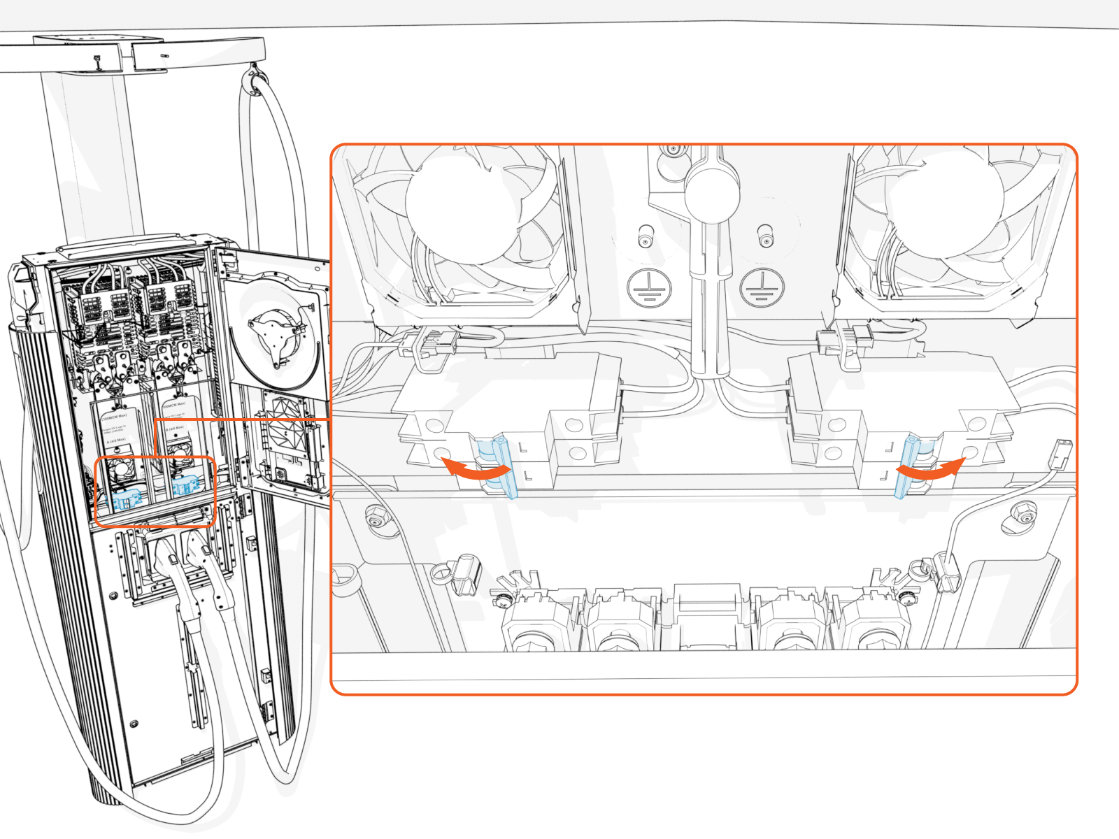
Primary breaker
Secondary breaker (if present)
Disengage the door stopper (x1 per upper and lower enclosure door).
.")
Quarter turn the door latches (x2 per upper and lower enclosure door).
The latch rotation direction shown in the illustration applies to Variation B Power Link 2000 units. For Variation A units, rotate each latch 90° counter-clockwise to lock the door. Refer to Appendix A: Variation Identification for further information.
.")
