Charging Cable (LCC and Non-LCC)
This section provides instructions for replacing the charging cable in the Power Link 2000.
Service instructions are given for both liquid cooled cables (LCC Liquid Cooled Cable) and non-LCC Liquid Cooled Cable.
| Liquid cooled cable (LCC Liquid Cooled Cable)
|
Non-LCC Liquid Cooled Cable
|
|
|
|
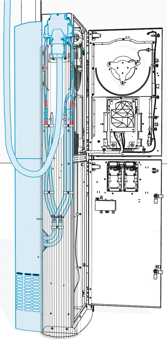
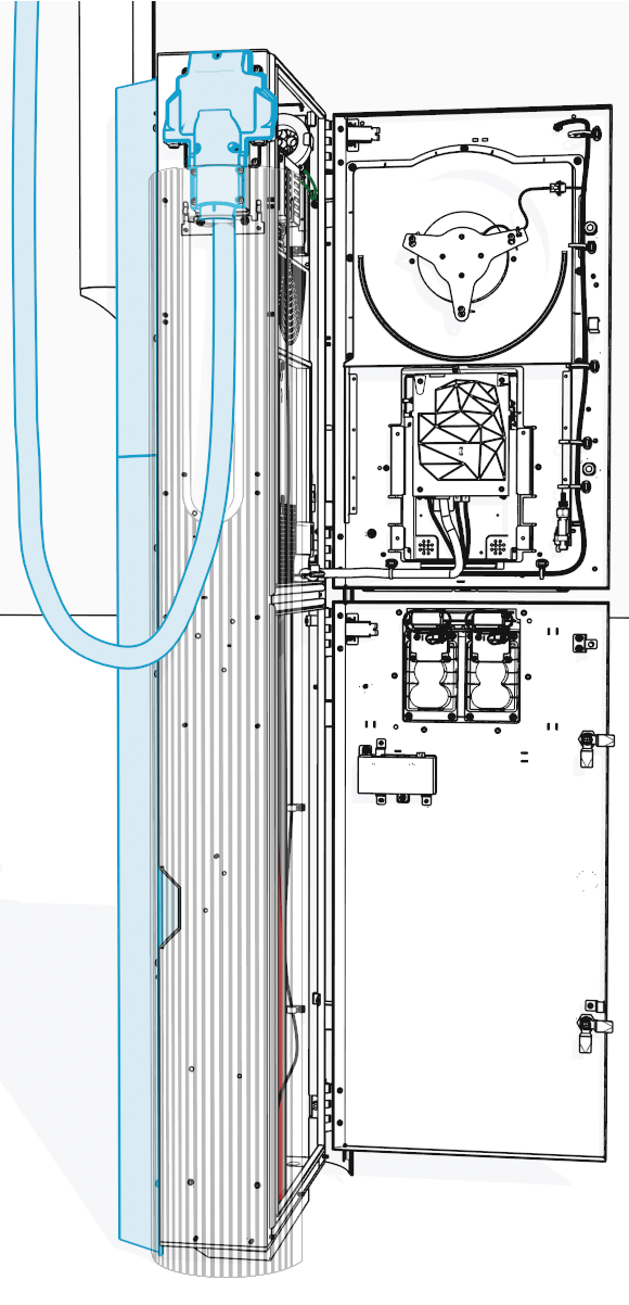
This warning applies only to Power Link 2000s certified for Eichrecht. On Power Link 2000 units certified for Eichrecht, the charging cable is not easily replaceable. As a standard practice, if replacing the charging cable, the Power Path Lug and the Control and Communication Module (CCOM)/Display must also be replaced. Removing these components breaks both the digital and physical sealing, which invalidates Eichrecht compliance and disables the station for public charging in affected jurisdictions. Only ChargePoint or qualified Instandsetzer (a technician certified for Eichrecht work) can replace these parts while preserving Eichrecht validity. You can identify an Eichrecht-certified Power Link 2000 by the "DE-M" mark on the nameplate.
Required Tools and Materials
|
|
Stepladder |
|
T20 Torx screwdriver |
|
|
T25 Security screwdriver |
|
Hex socket set (10 mm for ground and HV DC |
|
|
Clean rags (only for LCC |
|
ChargePoint coolant (only for LCC |
|
|
Funnel (only for LCC |
|
|

 v
v





Before You Begin
Before servicing the component, complete the following steps:
-
Remove these:
-
Open both the upper and lower doors.
The lower door only needs to be opened when servicing an LCC
Liquid Cooled Cable cable. It does not need to be opened for servicing a non-LCC Liquid Cooled Cable cable. -
Determine which charging cable (left or right) you want to replace.
-
Remove these:
-
Side panel (do not remove this if replacing a non-LCC
Liquid Cooled Cable cable)
After replacing the components, reverse the above steps to complete the service.
Replace the Charging Cable
To replace the charging cable, complete all steps given below.
Release the cable
-
Loosen the tetherball screw (if present).
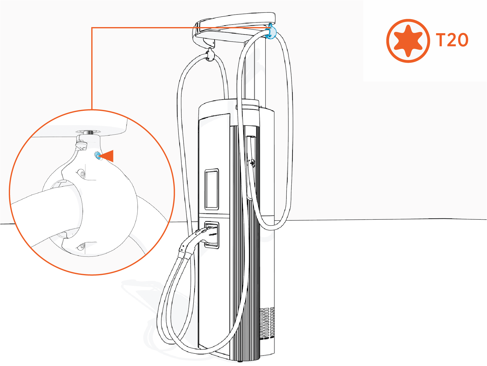
Torque to 2.8 Nm (25 in-lb).
-
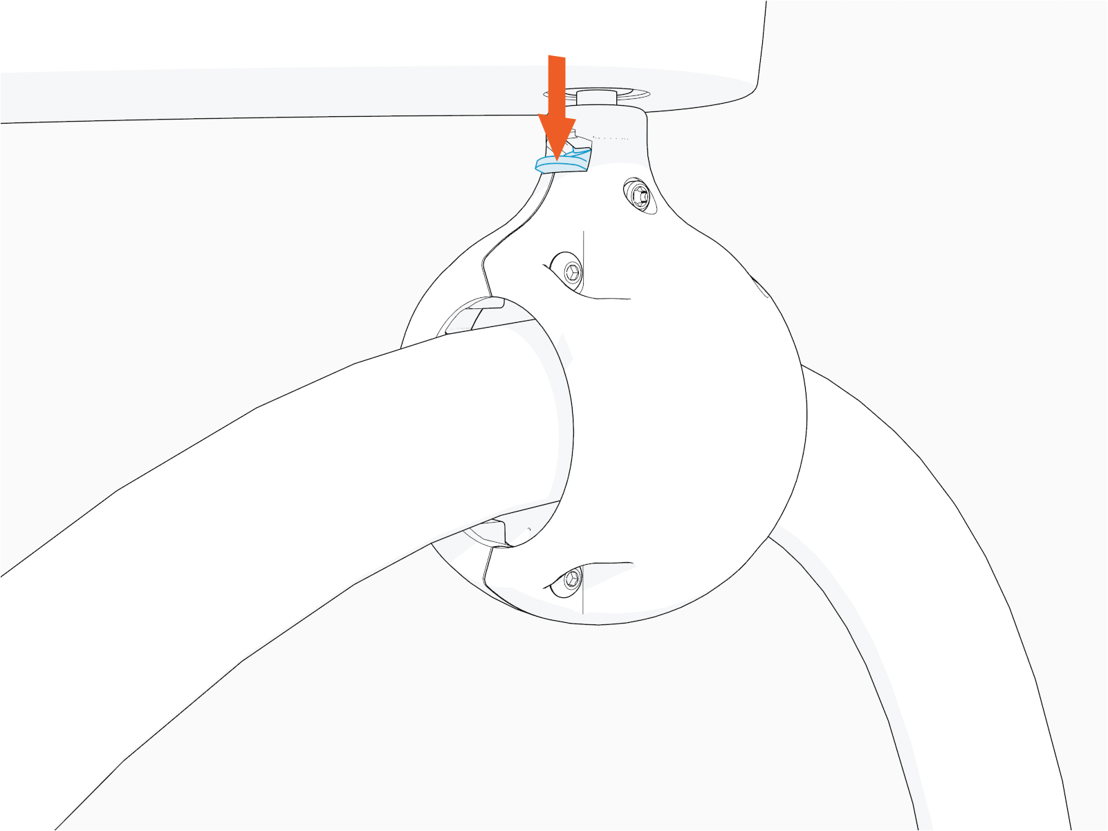
Hold the tetherball and gently push it up to unlatch the spring. The spring tab flips downward.
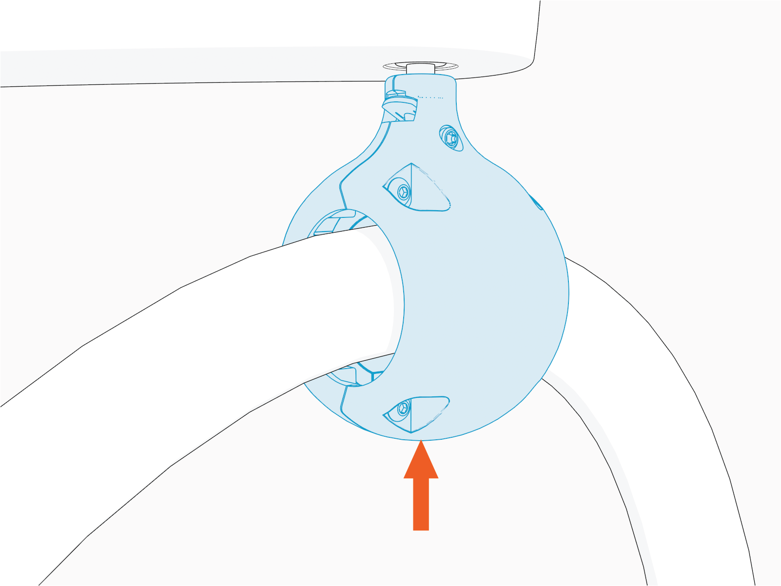
-
Hold down the spring tab.
-
Remove tetherball from the tether pin to release the cable.
Place the cable on a padded surface to avoid scratches on the cable's surface.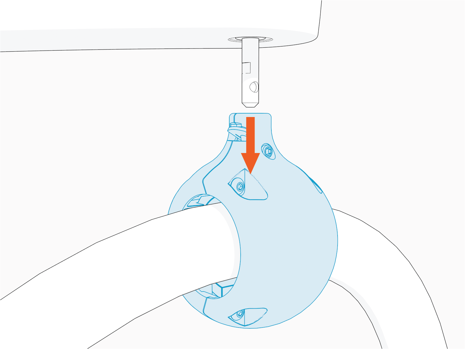 Align the spring with flat notch on the tether pin and gently push the tetherball onto the pin to suspend the cable as shown in the image below.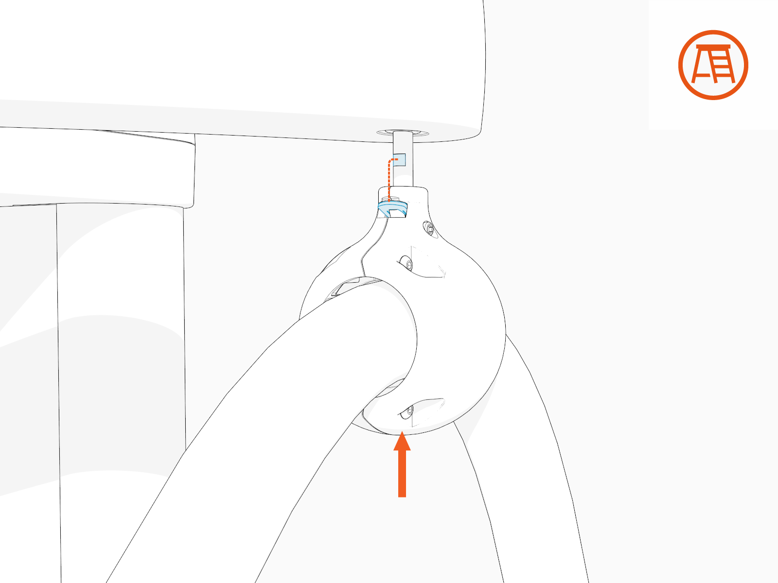
Replace the cable
-
Disconnect the wires and cables of a charging cable that you are replacing.
The illustrated cable connections on the left side and right side are for the left side and right side charging cables, respectively.
-
Press the latch and pull the connectors to disconnect the cables (x2; P238-23, and P317-2-06 or P317-1-06).
-
Remove the lug nuts (x4, per red and black HV DC
High Voltage Direct Current wires; and x1, per green ground wires).
Non-LCC
Liquid Cooled Cable wire and cable connections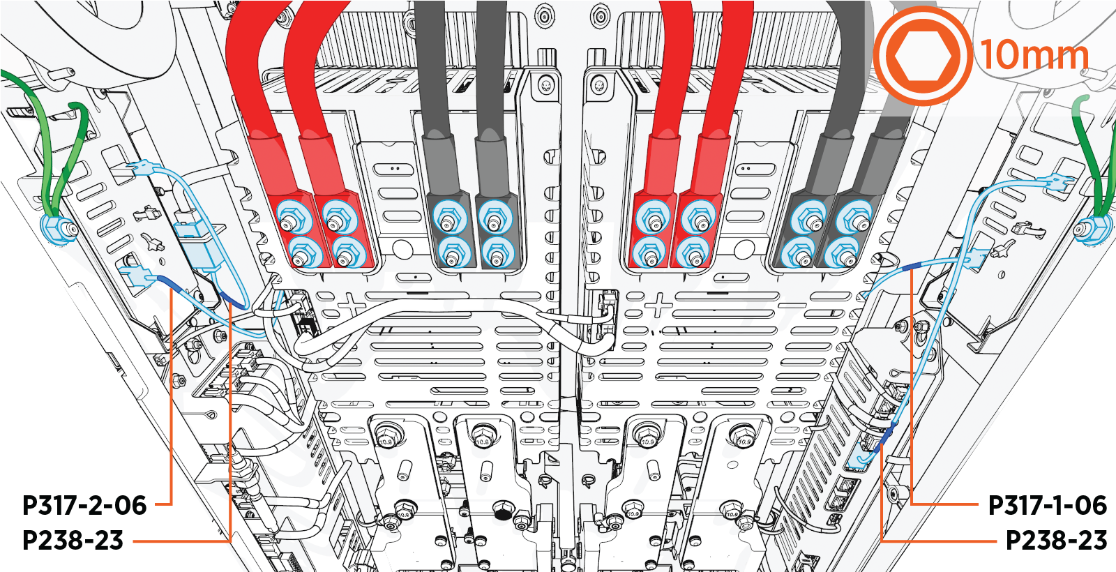
LCC
Liquid Cooled Cable wire and cable connections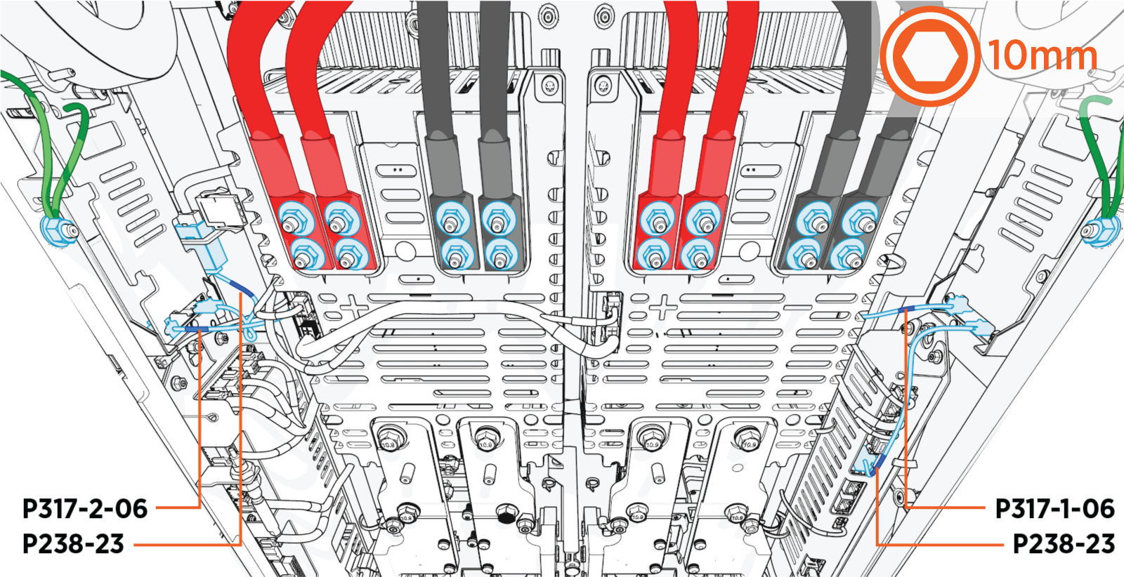
-
Connect red HV DC
High Voltage Direct Current wires to positive (+) and black HV DC High Voltage Direct Current wires to negative (-) pole. -
Torque all lug nuts to 5.6 Nm (50 in-lb).
-
Find the label on each cable to plug its connector back into its correct receptacle connector.
-
To reconnect, plug in. The connector latch must snap onto the receptacle with a click sound to ensure that the connection is secure.
-
-
(Skip this step for non-LCC
Liquid Cooled Cable) Press the latch and pull the connector to disconnect the hoses (x3, per charging cable).While disconnecting, use a clean rag to catch and wipe off any coolant residue on the connectors.
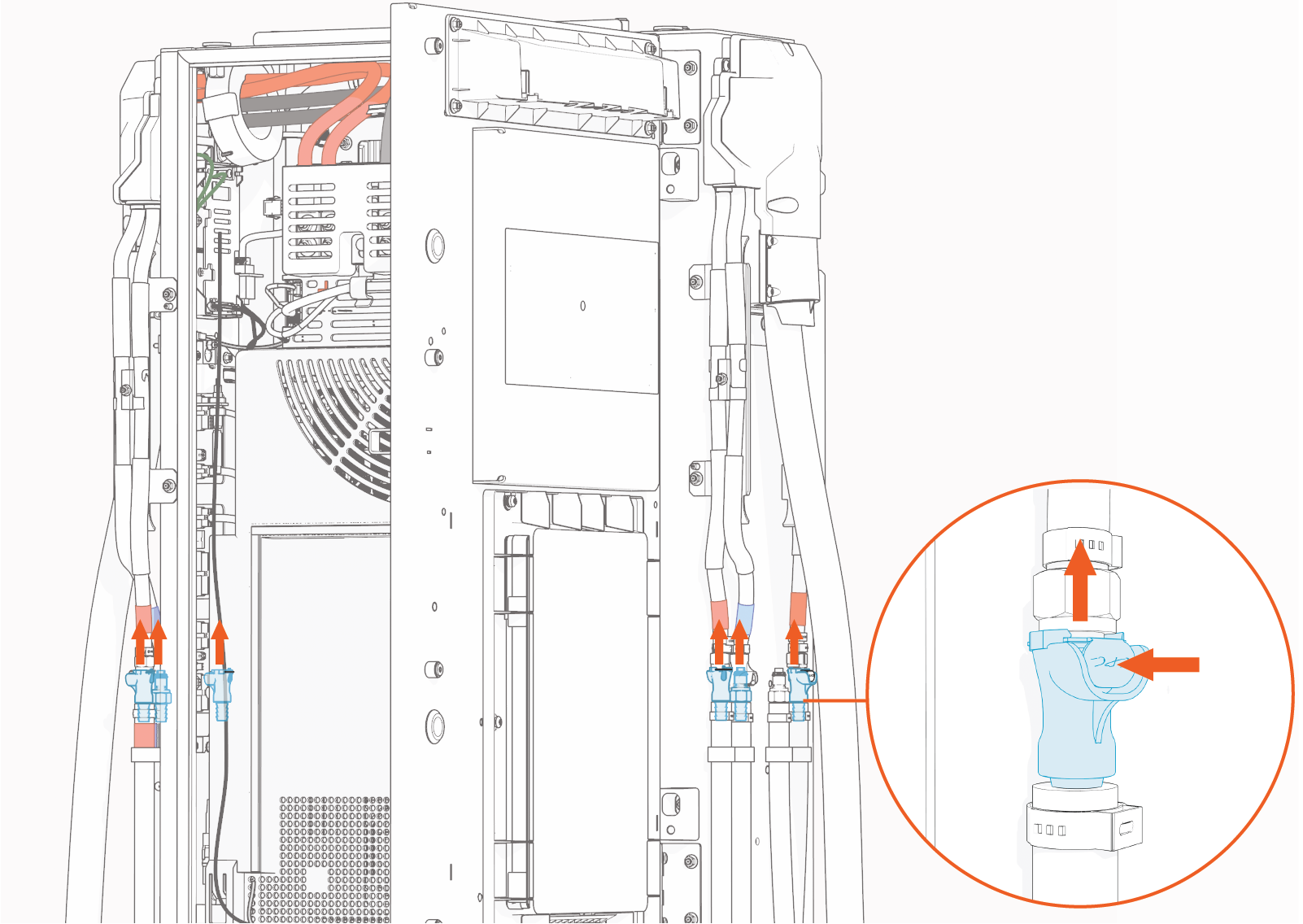
-
To reconnect, plug in. The connector latch must snap onto the receptacle with a click sound to ensure that the connection is secure.
-
-
(Skip this step for non-LCC
Liquid Cooled Cable) Remove the hex nuts (x2, per charging cable) to detach the coolant hose retaining clips.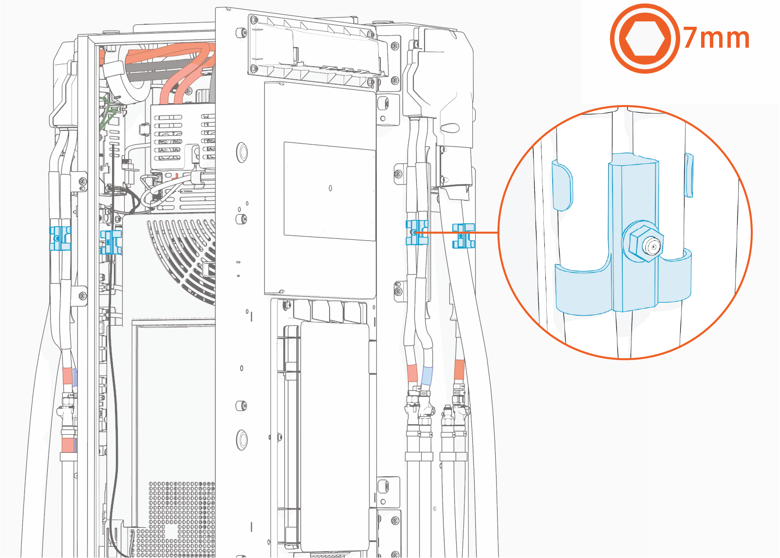
Torque these nuts to 1.7 Nm (15 in-lb).
-
Loosen the screws (x4, per charging cable).
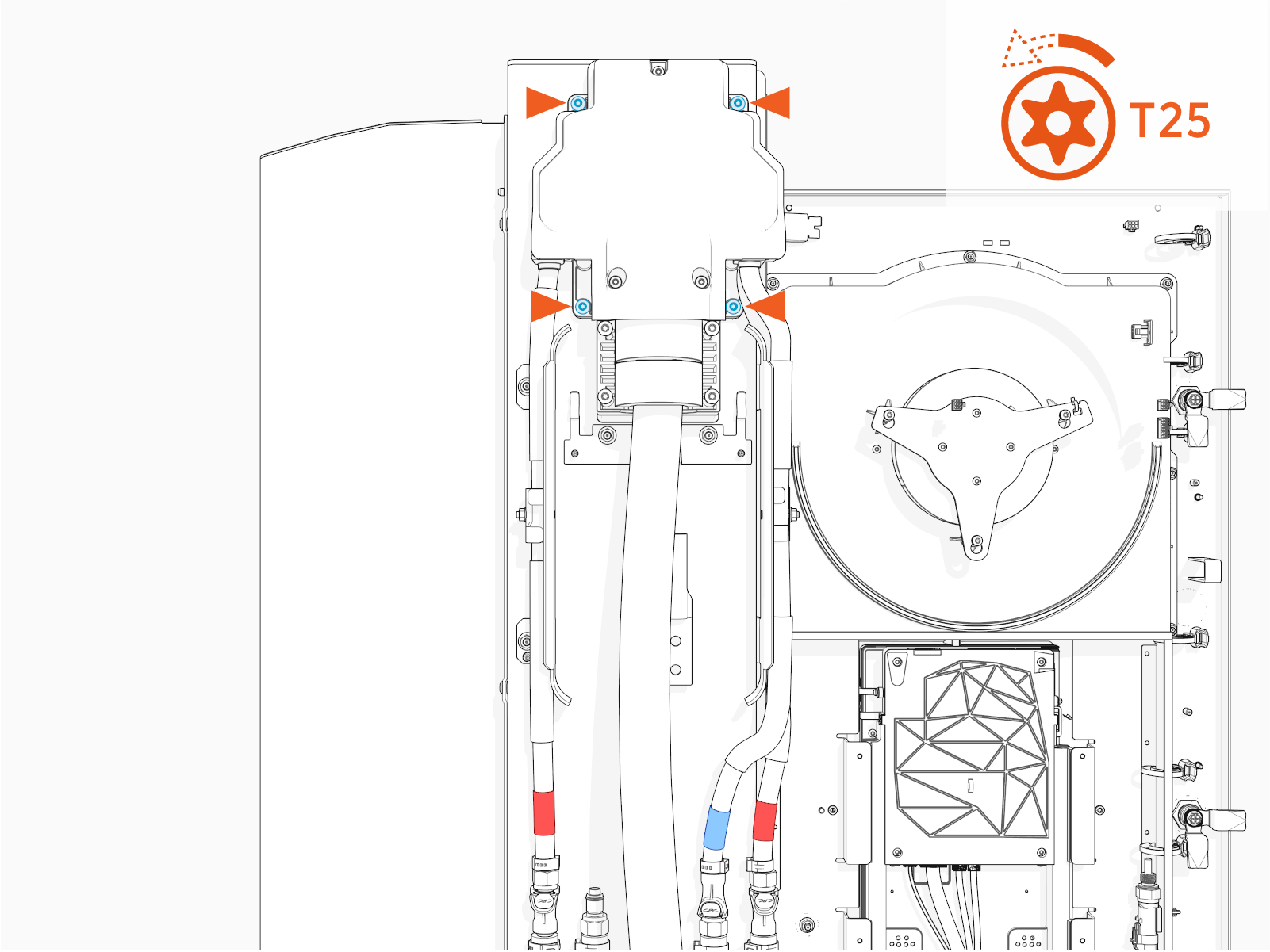
Torque these screws to 4.5 Nm (40 in-lb).
-
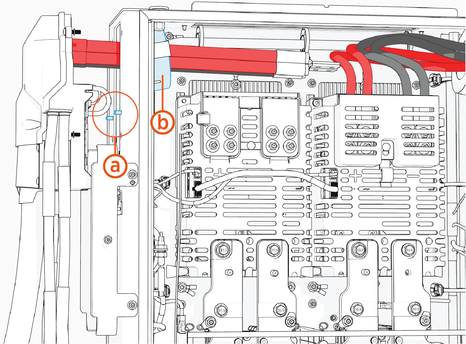
Remove cable assembly from studs (a) (x2) and route all wires out of the Power Link 2000.
-
Route only the positive (red) and negative (black) HV DC
High Voltage Direct Current wires through the Ferrite ring (b). Route the other wires below the Ferrite ring. -
Ensure no small cables get pinched between the charging cable assembly enclosure and the frame when installing.
-
Reverse the above steps to reinstall with replacement FRU Field Replaceable Unit.
- To adhere to ChargePoint best practices, complete the post-service checklist before you leave the site.
For assistance or to return a faulty part to ChargePoint, go to chargepoint.com/support and contact technical support using the appropriate region-specific number.
