Power Off
This section provides instructions for powering off the Power Link 2000.
Required Tools and Materials
|
|
Multimeter (meter and probes rated for 1000 V)
|
|
Lockout/tagout equipment |


Power Off the Station
You must be a ChargePoint Certified Technician to power off the charging station, or warranty limitations apply.
-
An Express or Express Plus configuration can have one or more power cabinets connected to one or more Power Link 2000s in what is called a cluster. Refer to the site's single line diagram (SLD) and identify the following:
-
All power cabinets and/or Power Link 2000s to be serviced.
-
All Power Link 2000s within the same cluster as the products identified above.
-
-
End all charging sessions on all Power Link 2000s identified in step above.
Failure to end the charging session before beginning service could damage hardware components. Such damaged components may need to be replaced.
-
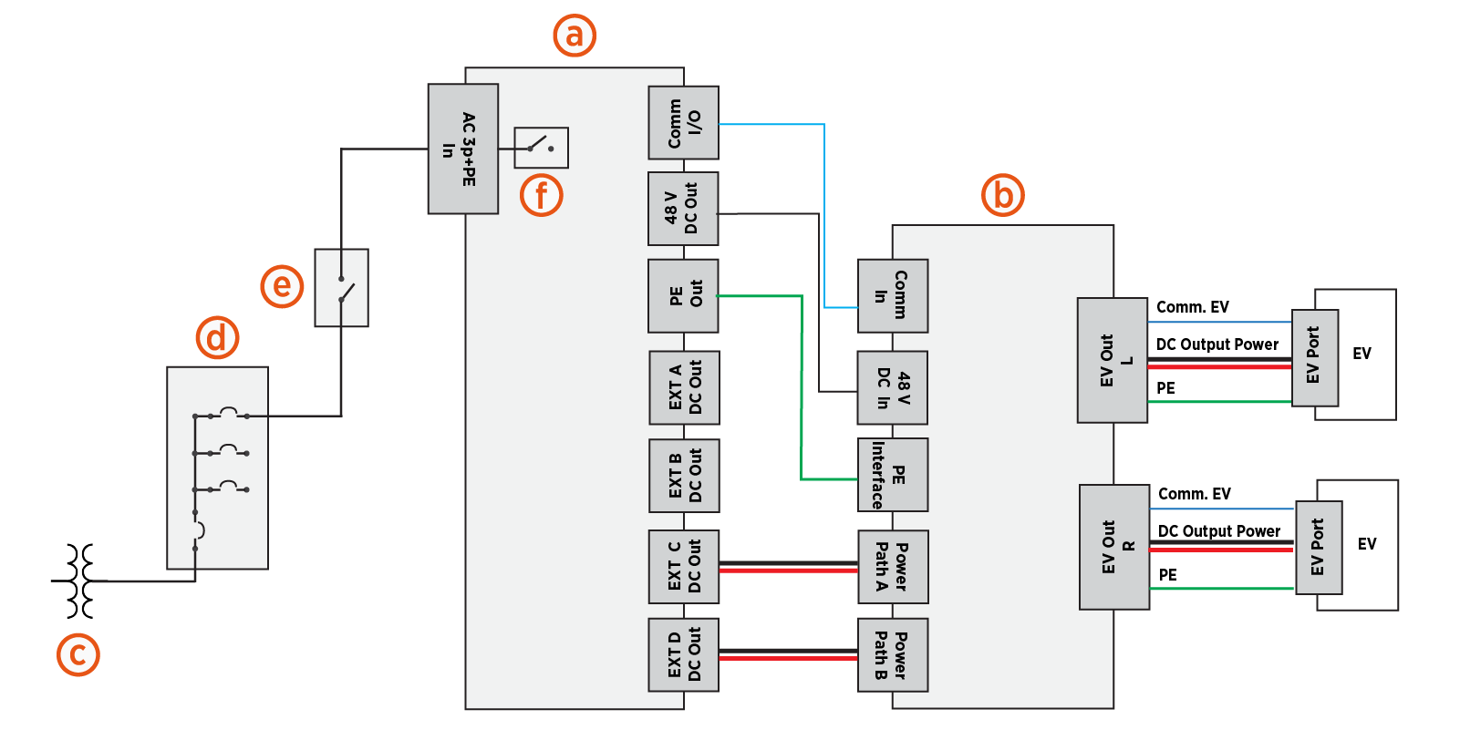
Determine where to disconnect power to the power cabinet(s). Refer to the site's SLD and identify the location of control elements such as circuit breakers and disconnect switches. The following illustration shows a sample electrical circuit for an Express cluster consisting of one Power Block 2000 feeding one Power Link 2000.
-
Power Block 2000 (sample power cabinet)
-
Power Link 2000
-
Transformer
-
Electrical panel with circuit breakers
-
External AC disconnect switch (optional)
-
Internal AC disconnect switch (included in some models; otherwise a product option)
There are three methods for disconnecting power:
-
If the power cabinet is equipped with an internal AC disconnect switch (f), turn the switch to the OFF position to power off power cabinet components and Power Link 2000s downstream of the switch. Refer to the power cabinet Operations and Maintenance Guide for instructions on AC disconnect switch usage.
-
At the site electrical panel, turn the circuit breaker (d) switch to the OFF position to power off all power cabinets and Power Link 2000s downstream of the breaker.
-
If an external AC disconnect switch (e) has been installed between power cabinet and the site electrical panel, turn the AC disconnect switch to the OFF position to power off all power cabinets and Power Link 2000s downstream of the AC disconnect switch.
-
Follow local code and refer to the site lockout/tagout procedure to de-energize the station.
-
Powering off the power cabinet will result in 48 V DC-connected Power Link 2000s losing power. Power Link 2000 can receive power from multiple power cabinets and may remain powered until all connected power cabinets are powered off.
-
A Power Link 2000 may be configured in a cluster wherein it receives DC power from multiple power cabinets. Be sure to power off all power cabinets in the cluster. Note that electrical hazard may still be present if Power Link 2000 is not powered, as 48 V DC and DC power path input may come from different power cabinets. Consult site drawings.
-
Ensure that the status light is off (unlit) for all de-energized power cabinets.
-
-
Wait for energy to dissipate (approximately five minutes).
Check Power Cabinet Status Light
Confirm the status light of all power cabinets supplying power to the Power Link 2000. Ensure the status light is completely off (not glowing). Refer to the applicable power cabinet Operations and Maintenance Guide for the location of the status light.
The status light provides an initial visual indication of power cabinet status but is not a confirmation that hazardous voltage is absent. Always perform the a voltage check at the power path input bus bars before servicing the Power Link 2000.
Verify the Power Link 2000 is De-Energized
Complete the following steps to verify the Power Link 2000 is de-energized:
-
Remove these:
-
Do not touch internal components without verifying that the Power Link 2000 is de-energized. Refer to the next step for verification details.
-
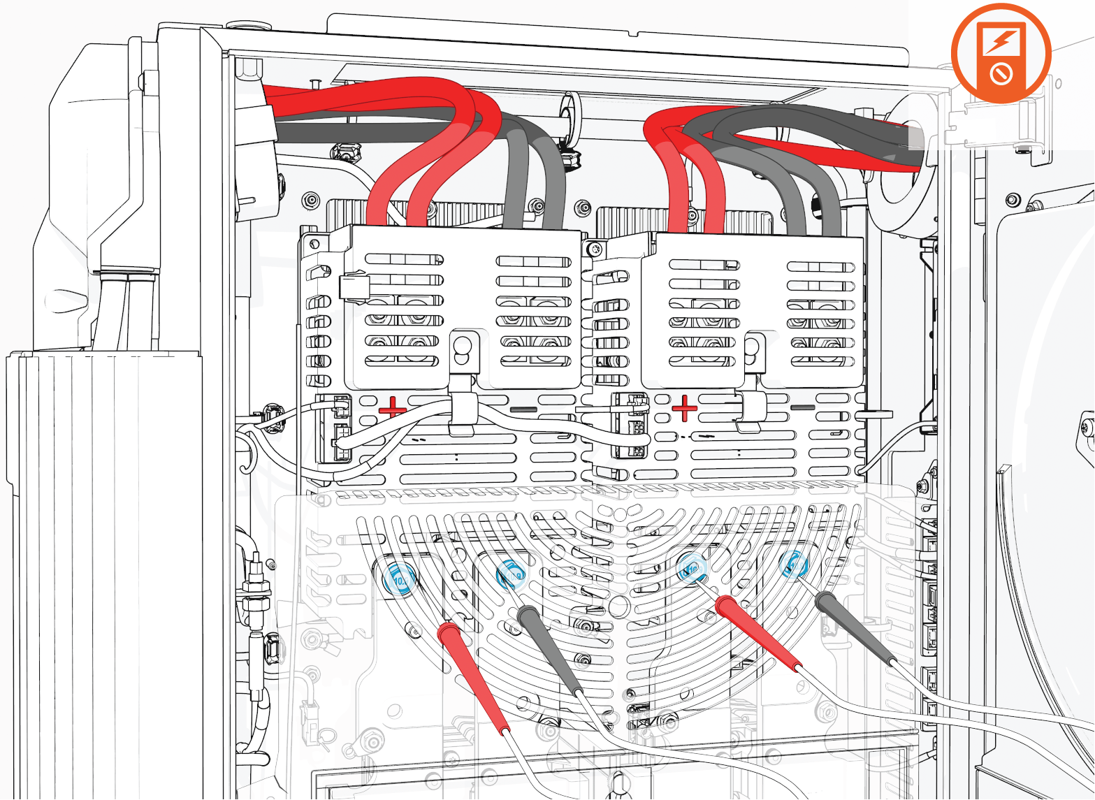
Hold the multimeter's probe tips against the DC power path bus bar bolts to verify that voltage is zero.
The illustration shows probe placement on the positive and negative bus bar bolts on the left-side and right-side power path assemblies. Power Link 2000 may be equipped with one or two power path assemblies. If two assemblies are present, verify zero voltage at both power path assemblies before servicing.