Control and Communication Module (CCOM)/Display
This section provides instructions for replacing the CCOM![]() Control and Communications Module and display in the Power Link 2000. Refer to the appropriate subsection below:
Control and Communications Module and display in the Power Link 2000. Refer to the appropriate subsection below:
-
8-Inch to 15-Inch Display Retrofit in Variation A Power Link 2000
-
8-Inch to 15-Inch Display Retrofit in Variation B Power Link 2000
To identify the Power Link 2000 variation, see Appendix A: Variation Identification.
This warning applies only to Power Link 2000s certified for Eichrecht. On Power Link 2000 units certified for Eichrecht, the CCOM![]() Control and Communications Module is not easily replaceable. As a standard practice, if replacing the CCOM
Control and Communications Module is not easily replaceable. As a standard practice, if replacing the CCOM![]() Control and Communications Module, the Power Path Lug and Charging Cable (LCC and Non-LCC) must also be replaced. Removing these components breaks both the digital and physical sealing, which invalidates Eichrecht compliance and disables the station for public charging in affected jurisdictions. Only ChargePoint or qualified Instandsetzer (a technician certified for Eichrecht work) can replace these parts while preserving Eichrecht validity. You can identify an Eichrecht-certified Power Link 2000 by the "DE-M" mark on the nameplate.
Control and Communications Module, the Power Path Lug and Charging Cable (LCC and Non-LCC) must also be replaced. Removing these components breaks both the digital and physical sealing, which invalidates Eichrecht compliance and disables the station for public charging in affected jurisdictions. Only ChargePoint or qualified Instandsetzer (a technician certified for Eichrecht work) can replace these parts while preserving Eichrecht validity. You can identify an Eichrecht-certified Power Link 2000 by the "DE-M" mark on the nameplate.
8-Inch CCOM/Display Replacement
This section provides instructions for replacing the 8-inch CCOM![]() Control and Communications Module and display in the Power Link 2000.
Control and Communications Module and display in the Power Link 2000.
Required Tools and Materials
|
|
8 mm hex socket |
|
T25 Security screwdriver |
|
|
Marker |
Before You Begin
Before servicing the component, complete the following steps:
-
Remove these:
After replacing the component, reverse the above steps to complete the service.
Replace the 8-Inch CCOM/Display
-
Ensure all cables connected to the CCOM
 Control and Communications Module are labeled as shown below.
 Depending on the Power Link 2000 configuration, there may be zero, one, two, or three USB
Universal Serial Bus cables connected to the CCOM Control and Communications Module.
-
P312-02
-
P312-08
-
ETH SURGE
Check the label on each cable to ensure cables are plugged into the correct port on the CCOM
Control and Communications Module. -
-
Disconnect all cables from the CCOM
Control and Communications Module.
Each cable has a latch on its terminating connector, except for the USB
Universal Serial Bus cables. Ensure the latch snaps into the CCOM Control and Communications Module receptacle connector with a click sound for a secure connection. -
Loosen the screws (x6) to remove the CCOM
Control and Communications Module/display cover. to remove the CCOM/display cover.")
Torque these screws to 2.8 Nm (25 in-lb).
-
Loosen the hex nuts (x4) and slide the CCOM
Control and Communications Module/display up to remove it from the door. and slide the CCOM/display up to remove it from the door.")
-
Torque these nuts to 4.5 Nm (40 in-lb).
-
Peel off the protective plastic film on the new CCOM
Control and Communications Module/display. -
Use care when handling the display.
The display is heavy and should not be dropped. -
Do not power on Power Link 2000 and contact ChargePoint Support to activate the new CCOM
Control and Communications Module. Find your region’s technical support number at chargepoint.com/support.CAUTION: Powering on Power Link 2000 without activating the new CCOM Control and Communications Module can cause a loss of station data on ChargePoint Platform Dashboard.
-
Reverse the above steps to reinstall with replacement FRU![]() Field Replaceable Unit.
Field Replaceable Unit.
- To adhere to ChargePoint best practices, complete the post-service checklist before you leave the site.
For assistance or to return a faulty part to ChargePoint, go to chargepoint.com/support and contact technical support using the appropriate region-specific number.
15-Inch CCOM/Display Replacement
This section provides instructions for replacing the 15-inch CCOM![]() Control and Communications Module and display in the Power Link 2000.
Control and Communications Module and display in the Power Link 2000.
Required Tools and Materials
| T20 Screwdriver |
| Marker |
Before You Begin
Before servicing the component, complete the following steps:
After replacing the component, reverse the above steps to complete the service.
Replace the 15-Inch CCOM/Display
Ensure all cables connected to the CCOM
Control and Communications Module are labeled as shown below. Depending on the Power Link 2000 configuration, there may be zero, one, two, or three USB
Universal Serial Bus cables connected to the CCOM Control and Communications Module.

P312-02
P312-08
ETH SURGE
Check the label on each cable to ensure cables are plugged into the correct port on the CCOM
Control and Communications Module.Disconnect all cables from the CCOM
Control and Communications Module.
Each cable has a latch on its terminating connector, except for the USB
Universal Serial Bus cables. Ensure the latch snaps into the CCOM Control and Communications Module receptacle connector with a click sound for a secure connection.Loosen the screws (x6).
 and slide the CCOM/display up to remove it from the door.")
Torque these screws to 2.8 Nm (25 in-lb).
Slide the CCOM
Control and Communications Module/display up to remove it from the door.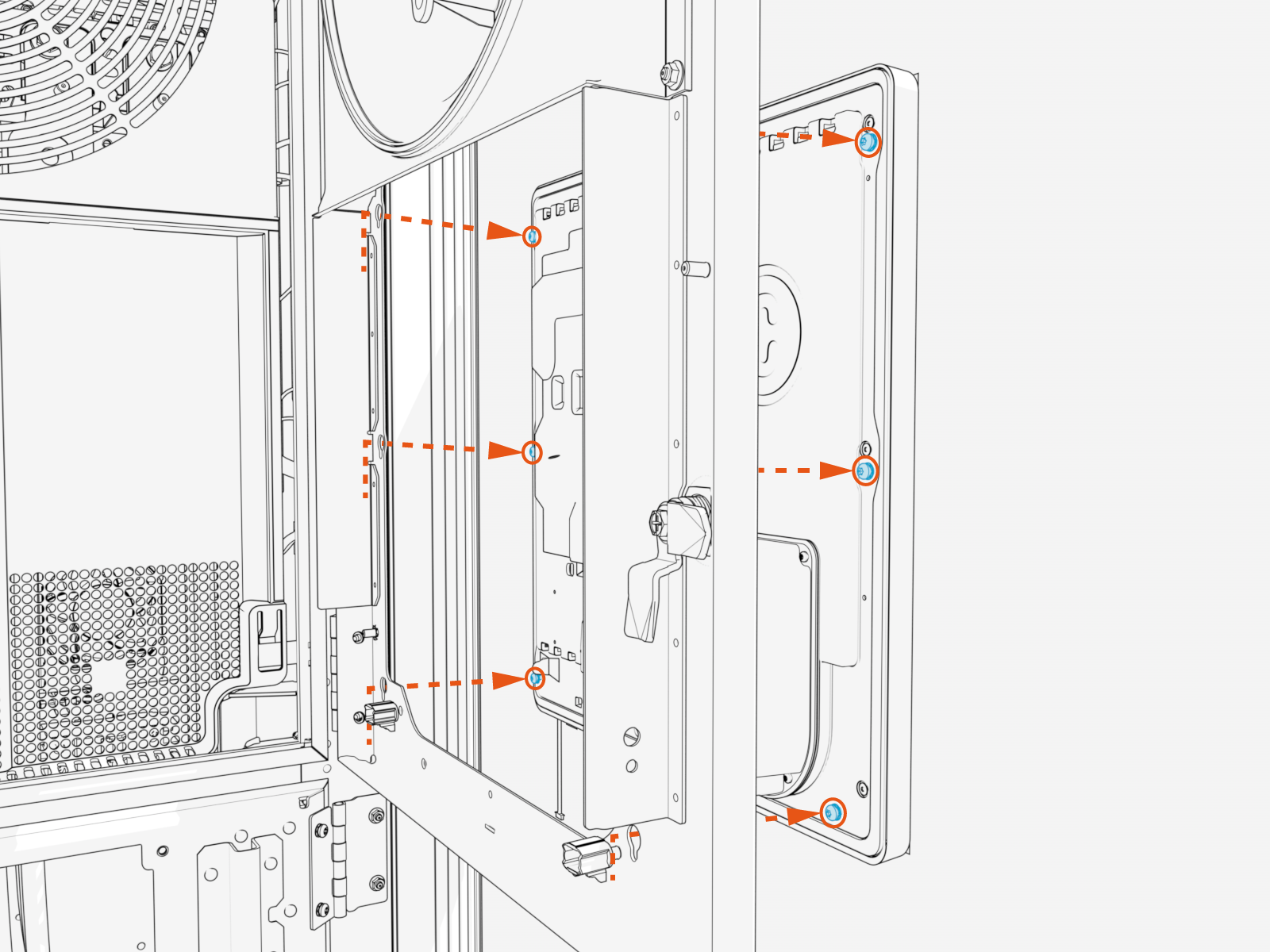
Peel off the protective plastic film on the new CCOM
Control and Communications Module/display.Use care when handling the display.
The display is heavy and should not be dropped.Do not power on Power Link 2000. Contact ChargePoint Support to activate the new CCOM
Control and Communications Module. Find your region’s technical support number at chargepoint.com/support.CAUTION: Powering on Power Link 2000 without activating the new CCOM Control and Communications Module can cause a loss of station data on ChargePoint Platform Dashboard.
Reverse the above steps to reinstall with replacement FRU![]() Field Replaceable Unit.
Field Replaceable Unit.
- To adhere to ChargePoint best practices, complete the post-service checklist before you leave the site.
For assistance or to return a faulty part to ChargePoint, go to chargepoint.com/support and contact technical support using the appropriate region-specific number.
8-Inch to 15-Inch Display Retrofit in Variation A Power Link 2000
This section provides instructions for retrofitting an 8-inch display with a 15-inch display in a Variation A Power Link 2000. If working with a Variation B Power Link 2000, see 8-Inch to 15-Inch Display Retrofit in Variation B Power Link 2000. To identify the Power Link 2000 variation, see Appendix A: Variation Identification.
Required Tools and Materials
| T20 Torx screwdriver |
| T25 Security screwdriver |
| 10 mm hex socket |
| Marker |
Before You Begin
Before servicing the component, complete the following steps:
Disconnect the CCOM Cables
Ensure all cables connected to the CCOM
Control and Communications Module are labeled as shown below. Depending on the Power Link 2000 configuration, there may be zero, one, two, or three USB
Universal Serial Bus cables connected to the CCOM Control and Communications Module. P312-02
P312-08
ETH SURGE
Disconnect all cables from the CCOM
Control and Communications Module.
Prepare for Door Replacement
The 15-inch CCOM![]() Control and Communications Module/display requires a new door to be installed. To prepare for door replacement, complete the following steps:
Control and Communications Module/display requires a new door to be installed. To prepare for door replacement, complete the following steps:
Unplug the area downlight cable connector from the door.

Disconnect cable harness clips (x5) from the door.
 from the door.")
Remove the temperature sensor from the door.

Disconnect the ground wire from the door. Save the nut for later use.

Store the cable harnesses within the station body.
The cables must be stored within the station body to avoid damaging the cables.
Replace the Door
Remove M5 screws (x4) at door hinges to remove the existing door.
 at door hinges to remove the existing door.")
Align the replacement door (with larger opening for 15-inch display) to the Power Link 2000 frame and secure it with M5 screws (x4) at the door hinges. Torque to 4.5 Nm (40 in-lb).
 to the Power Link 2000 frame and secure it with M5 screws (x4) at the door hinges. Torque to 4.5 Nm (40 in-lb).")
Mount 15-Inch Display
Align and seat the 15-inch CCOM
Control and Communications Module/display fasteners into the keyholes on the door.
Tighten the fasteners (x6). Torque to 2.8 Nm (25 in-lb).
. Torque to 2.8 Nm (25 in-lb).")
Reinstall Connections to the Door
Reinstall connections to the door.

Connect the ground wire (with nut saved from prior removal).
Install the temperature sensor.
Connect the cable harness clips (x5).
Connect the downlight cable connector.
Torque the ground wire nut to 5.6 Nm (50 in-lb).
Connect cables to the 15-inch CCOM
Control and Communications Module.IMPORTANT:Check the label on each cable to ensure cables are plugged into the CCOM
Control and Communications Module as shown below. The cable port locations are reversed between the 8-inch CCOM Control and Communications Module and 15-inch CCOM Control and Communications Module.Each cable has a latch on its terminating connector, except for the USB
Universal Serial Bus cables. Ensure the latch snaps into the CCOM Control and Communications Module receptacle connector with a click sound for a secure connection.

P312-02
P312-08
ETH SURGE
The 15-inch CCOM
Control and Communications Module requires a Smart Antenna to function. Check if the Power Link 2000 is equipped with a Smart Antenna (highlighted in the illustration below). If needed, install a Smart Antenna.
Reverse the initial steps taken to power off and open the Power Link 2000, with the following modifications:
When reinstalling the front cover, install the new front cover with larger opening for the 15-inch display.

Do not power on the Power Link 2000 and contact ChargePoint Support to activate the new CCOM
Control and Communications Module.CAUTION: Powering on without activating the new CCOM Control and Communications Module can cause a loss of station data on ChargePoint Platform.After successful power on, complete the post-service checklist.
8-Inch to 15-Inch Display Retrofit in Variation B Power Link 2000
This section provides instructions for retrofitting an 8-inch display with a 15-inch display in a Variation B Power Link 2000. If working with a Variation A Power Link 2000, see 8-Inch to 15-Inch Display Retrofit in Variation A Power Link 2000. To identify the Power Link 2000 variation, see Appendix A: Variation Identification.
Required Tools and Materials
| T20 screwdriver |
| T25 Security screwdriver |
| 8 mm hex socket |
| Marker |
Before You Begin
Before servicing the component, complete the following steps:
Disconnect the CCOM Cables
Ensure all cables connected to the CCOM
Control and Communications Module are labeled as shown below. Depending on the Power Link 2000 configuration, there may be zero, one, two, or three USB
Universal Serial Bus cables connected to the CCOM Control and Communications Module. P312-02
P312-08
ETH SURGE
Disconnect all cables from the CCOM
Control and Communications Module.
Remove the 8-Inch Display
To remove the 8-inch display, complete the following steps:
Loosen the screws (x6) to remove the display cover.
Loosen the hex nuts (x4) and slide the display up to remove it from the door.
Remove the Adapter Bracket
To remove the adapter bracket, complete the following steps:
Remove adapter bracket fasteners (x6).
.")
Disconnect main cable harness clips (x2) from the door.
 from the door.")
Remove the temperature sensor from the door.

Pull adapter bracket downward to remove.
The top of the bracket has an anchor stud (a) that must pull out of the door frame.

Mount the 15-inch Display
To mount the 15-inch display, complete the following steps:
Align and seat the 15-inch CCOM
Control and Communications Module/display fasteners into the keyholes on the door.Tighten the fasteners (x6). Torque to 2.8 Nm (25 in-lb).
Reinstall Connections to the Door
Reinstall connections to the door.

Connect the main cable harness clips (x2).
Install the temperature sensor.
Connect cables to the 15-inch CCOM
Control and Communications Module.IMPORTANT: Check the label on each cable to ensure cables are plugged into the CCOM Control and Communications Module as shown below. The cable port locations are reversed between the 8-inch CCOM Control and Communications Module and 15-inch CCOM Control and Communications Module. P312-02
P312-08
ETH SURGE
Reverse the initial steps taken to power off and open the Power Link 2000, with the following modifications:
Do not power on the Power Link 2000 and contact ChargePoint Support to activate the new CCOM
Control and Communications Module.CAUTION: Powering on Power Link 2000 without activating the new CCOM Control and Communications Module can cause a loss of station data on ChargePoint Platform Dashboard.After successful power on, complete the post-service checklist.
