Safely Inspecting Express 250 with High Voltage
To safely measure 480 V AC/400 V AC incoming voltage, complete the steps in this chapter.
Required Tools and Materials
|
|
Head lamp |
|
T25 Torx security screwdriver |
|
|
Wire strippers |
|
Multimeter (CAT III 600 V and above rated) and |
|
|
Cabletie |
|
Phillips screwdriver |
|
|
Flat head screwdriver |
|
Wire cutters |
|
|
Appropriate PPE including hard hat, face shield, safety glasses coveralls, leather boots, and rubber insulated gloves |
|
8 mm (5/16 mm) nut Torque screwdriver |
|
|
Insulation resistance measurement tool: Megger tester is commonly used |
|
Wago tool (contact ChargePoint support if this tool is needed): 5.5mm Blade, 0.8mm Tip Wago operating tool |
Measuring 480 V AC on Express 250
The following are the possible reasons to measure incoming 480 V AC on a system:
-
Functioning normally but suspected to have occasional grid side disturbance.
-
PMs faulting with over voltage or overcurrent on a regular basis.
-
Log analysis shows high line or close to 480 V AC + 10% (EU: 400 V AC – 10%) on the incoming voltage that needs inspection.
-
Suspected weak grid condition that needs input power monitoring.
Procedure to Measure 480 V AC
To safely measure, perform the following steps:
-
Power off the system using Disconnect panel or the Switchgear. Follow appropriate PPE rules based on the rule of the land while handling the high voltage disconnect. Lockout and tagout the upstream breaker or disconnect before accessing the dispenser.
FAILURE TO FOLLOW THESE INSTRUCTIONS CAN RESULT IN SERIOUS INJURY OR LOSS OF LIFE. -
Use steps from Service Bulletin: AC Wiring Verification to open the top panels and gain access to the surge arrestor block. Refer the following image for reference.

-
Power up the system after wearing the required PPE.
Use the essential PPE while accessing a live high voltage system. -
Use the standard tip probe to measure AC voltage on the surge arrestor block.
-
Measure and document the voltages across all phases and phase to GND
 Ground points as per the below table.
 V(L1-L2) V(L2-L3) V(L3-L1) V(L1-GND Ground)V(L2-GND Ground)V(L3-GND Ground)Measured Voltage _292x262.png)
_290x320.png)
-
Power down the station using appropriate PPE after the voltages are measured.
-
Report the measured voltages to the ChargePoint customer support team for further feedback from engineering.
-
Reassemble the Express 250 and power it back ON with appropriate PPE, until further instructions from ChargePoint.
Extended Power Quality Measurement
If ChargePoint Engineering team requests for an extended power quality measurement at site, perform the following steps:
- Request the site drawing to understand the Power Infrastructure and all the loads connected to the same grid/transformer.Use the essential PPE while accessing a live high voltage system.
-
Verify if Express 250 is connected to a Disconnect or a Switchgear panel. It is advised to perform longer AC grid Power Quality Monitoring outside of the dispenser.
-
Power down the main breaker using appropriate PPE prior to accessing any High Voltage component. Lockout and tag out the upstream breaker before accessing the dispenser.
FAILURE TO FOLLOW THESE INSTRUCTIONS CAN RESULT IN SERIOUS INJURY OR DEATH. -
Measure across accessible points to confirm the absence of High Voltage (<1 V) prior to connecting Power Quality Measuring device.
-
Connect the 3-phase voltage and 3-phase current probes from the Power Quality Meter to the available points to monitor the grid conditions. The location of where the device can be left is dependent on each site and size of the measuring device. Take all safety precautions while leaving the Power Quality Meter unattended.
-
Retrieve the data after the stipulated time (as directed by Engineering team.
Measuring 480 V AC on Express 250 Suspected with Electrical Event
The voltage should be measured for the following cases:
-
AC side breaker trip event: Resetting tripped breaker is allowed only once prior to extended system troubleshooting.
-
System losing power randomly (with or without an indication of an electrical event): If the user notices unexpected system shut down events, then extended troubleshooting is needed after two such occurrences.
-
Express 250 reports surge fault, breaker trip, isolation fault: Contact engineering to determine if any AC side troubleshooting is needed case by case.
-
PMs fail to recover after reporting faults related to grid event: Contact engineering to determine if AC side troubleshooting is needed case by case
-
AUXPS reports AC over/under voltage faults
Procedure to Measure 480 V AC with Electrical Event
Perform the following steps to measure 480 V AC with suspected electrical event:
-
Power off the system using Disconnect panel or the Switchgear. Follow appropriate PPE rules based on the rule of the land while handling the high voltage disconnect. Lockout and tagout the upstream breaker or disconnect before accessing the dispenser.
FAILURE TO FOLLOW THESE INSTRUCTIONS CAN RESULT IN SERIOUS INJURY OR LOSS OF LIFE. -
Confirm if the voltage is less than 1V when disconnected or upstream to the system, prior to opening the dispenser. If unable to determine absence of high voltage upstream to the system, then wait for at least 10 minutes before accessing the system (to allow discharge of internal capacitors).
-
Use steps from Service Bulletin: AC Wiring Verification to open the top skin to gain access to the surge arrestor block (see images from Procedure to Measure 480 V AC).
-
Confirm the absence of high voltage (< 1 V) across the surge arrestor, before opening the rest of the skin on the dispenser and the side cover that covers the AC terminal wago connectors.
-
Visually inspect the whole station for any signs of electrical or thermal damage. Document all the findings along with clear photos. Contact ChargePoint support if any damage is found. Refer the below images for examples of electrical events seen on Express 250.

-
Visually check each wire in the AC terminal block: L1, L2, L3, and GND
Ground (protective earth). Check the local code to see if Neutral is needed. A neutral connection is not required for service equipment operation. -
Perform pull test on all the cables to ensure they are seated correctly and locked in place.
-
Measure continuity between each of the phases (L1-L2, L2-L3, L3-L1) and phase-GND
Ground (L1-GND Ground, L2-GND Ground, L3-GND Ground). Confirm that there is no short with the above measurements. Multimeter should read OL indicating an Open Loop. If there are any issues, document the findings along with clear photos and reach out to ChargePoint support. -
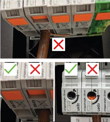
Verify if there are any strands of exposed copper below the terminal and that all the strands are fully inserted. Also, confirm if the Wago connectors are fully closed. Refer to the below image to confirm.
-
If there are no issues, perform an insulation resistance test using a Megger or other suitable instrument on the AC cables to ensure there is no break in isolation of the cable. You may perform a 1000 V DC insulation‑resistance test with a 2‑minute hold, where a reading around 20 MΩ indicates healthy insulation.
-
Use the Wago tool to disconnect the cables from the system before performing Insulation resistance test.
-
Connect one lead to each wire pair (L1-L2, L2-L3, L3-L1, L1-GND
Ground, L2-GND Ground, L3- GND Ground) and run test. Reinstall the wires. -
Report findings to engineering for further feedback.
Using a flat head screwdriver or similar tool may cause damage to the Wago. ChargePoint will not warranty this damage. Costs to replace will be invoiced to the servicing company. -
Do not power on the system until further instructions are given from ChargePoint.
