Replace the Touchscreen (CPNK)
To replace the touchscreen (CPNK![]() ChargePoint Networking Kit Board), complete the steps in this chapter.
ChargePoint Networking Kit Board), complete the steps in this chapter.
Required Tools and Materials
|
|
Head lamp |
|
T25 Torx security screwdriver |
|
|
Stepladder |
|
The packing slip from the replacement part package (contains configuration information) |
|
|
ChargePoint replacement part for your region:
|
Before you Begin
Complete the following procedures:
Remove the Touchscreen
-
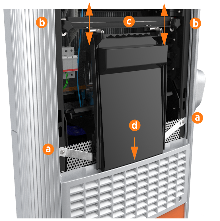
Use a T25 Torx driver to remove the M5 screw and washer attaching each touchscreen ground strap to the frame. Keep the screws and washers for reuse.
-
Loosen both retention knobs (b), allowing the touchscreen beam (c) to slide up vertically and the touchscreen’s bottom edge to clear the middle vent panel’s slot (d).
-
With hand pressure, tilt the touchscreen upward at a 45-degree angle.
-
Allow the touchscreen to return to its lowest position vertically.
The bottom edge and corners of the touchscreen are sharp. Take care when moving underneath the raised screen. -
Disconnect all cables from the connectors on the bottom of the touchscreen and remove them from the wire management rings.
Leave the touchscreen tilted up only when necessary to improve visibility and access to the repair area during service procedures. -
While supporting the touchscreen, continuously rotate the touchscreen’s knobs counterclockwise until they are completely removed. Remove the touchscreen from the station.
Replace the Touchscreen
-
Align the hooks of the new touchscreen’s mounting bracket over the retention knob supports. Tighten the knobs enough to secure the touchscreen.
-
Connect all cables to the underside of the touchscreen:
-
Proximity sensor cables x 2 (connect left wire to left port, right wire to right port)
-
Speaker cable
-
Europe only: meter cable (if applicable)
-
24 V DC cable
-
CAT CPNK
 ChargePoint Networking Kit Board to DCC Dispenser Charge Controller (Station Management Unit)
 -
LED Display cable (USB
Universal Serial Bus-A)
Perform a pull-push test to ensure that each cable is correctly seated. Failure to connect these correctly could prevent the system from powering on. -
-
Connect the proximity sensor wires on the middle vent panel to the corresponding connectors on the bottom of the touchscreen: left wire to left port and right wire to right port.
-
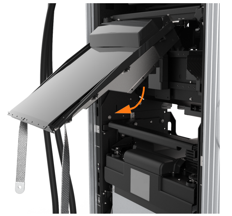
Route any excess wiring through the right-side wire management ring under the touchscreen, to prevent it being pinched in the panels.

-
Route all other cables through the wire management rings on the underside of the touchscreen.
Ensure all wires are neatly organized and pressed toward the back of the Express 250 to allow the touchscreen to be easily lowered into the slot on the middle vent panel. Ensure the wires are not pinched between the touchscreen and the vent panel. -
With hand pressure, swing the touchscreen down. Loosen both retention knobs (b), allowing the touchscreen beam (c) to slide up vertically. Re-tighten the knobs at the highest position. Tilt the bottom of the touchscreen inside the slot in the middle vent panel, aligning the notch in the center of the bottom edge (d) to the guide ridge inside the panel slot.
-
Keeping pressure on the edge of the touchscreen to properly seat it inside the panel, loosen the knobs to lower the screen again.
-
With both hands, hold the beam (c) and rotate the top of the bar away from you to relieve stress at the retention knobs. Re-tighten the knobs to secure it.
-
Use a T25 Torx driver to replace the M5 screw and washer (a) attaching each touchscreen ground strap to the frame.
-
Torque to 4 Nm (35 in-lb).
REVERSE THE ABOVE STEPS TO REPLACE THE TOP FRONT PANEL, LED DISPLAY, AND AREA LIGHT BAR.
