Replace the Swing Arm Assembly
To replace the swing arm assembly, complete the steps in this chapter.
Required Tools and Materials
|
|
Head lamp |
|
T20 and T25 Torx security screwdriver |
|
|
Stepladder |
|
Torque paint pen |
|
|
C - Clamp |
|
#2 Phillips screwdriver |
|
|
Flat head screwdriver |
|
10 mm (3/8 in) hex wrench |
|
|
Dielectric grease |
|
Forklift |
|
|
Thin piece of cardboard, about 25 mm (1 in) long x 12 mm (0.5 in) wide x 3 mm (0.1 in) thick |
|
8 mm (5/16 mm) nut Torque screwdriver |
|
|
10 mm (3/8 in) socket |
|
Torque wrenches capable of measuring torques from 2.8 Nm (25 in-lb) to 6.8 Nm (60 in-lb) |
|
|
CCS1/CHAdeMO: ChargePoint replacement part #CPE250-CABLE-CCS1-CHD-FCPE250 |
|
CCS2/CHAdeMO: ChargePoint replacement part #CPE250-CABLE-CCS2-CHD-FCPE250 |
|
|
CCS1/CCS2: ChargePoint replacement part #CPE250-CABLE-CCS1-CCS2-FCPE250 |
Before you Begin
Complete the following procedures:
Remove the Right Extrusion
-
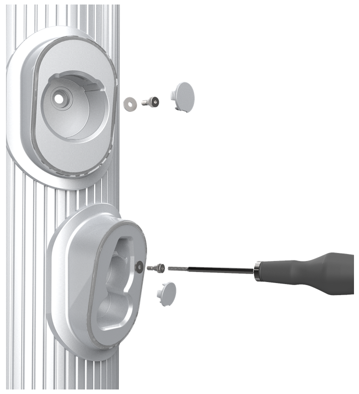
Remove the charging cables from their holsters and rest them gently on a padded surface out of the way.
-
Insert a small flathead screwdriver into the notch on each plastic cap to remove it from the holster screw opening.
-
Use a T25 Torx to remove the rubberized washer and M5 shoulder screw. Set them aside for reuse.
-
Using a step ladder, hold the extrusion with one hand and loosen the top two captive screws using the supplied T25 Torx driver.

The top and middle screws are asymmetrical.
-
Use a T25 Torx driver to loosen the middle two captive screws while the Power Module mechanism is still in the closed position.

-
Use a T25 Torx driver to loosen the bottom two captive screws.

-
Slightly tilt the bottom of the extrusion out to extract its top edge from under the bottom edge of the area light bar. Lift the extrusion off the guide pins on each side of the frame that hold the extrusion in place.

-
Disconnect the shortest cable from the top holster.
-
Disconnect the next-longest cable from the bottom holster.

When reinstalling, check that these connections are correctly seated, or the system will not operate.
-
Locate the P-clip mounted to one of the holsters (top or bottom holster varies by product version).
-
Remove the P-clip hardware from the extrusion holster:
-
Generation 1, attached with screw: use a T25 Torx driver to remove the screw and all its components. Carefully note the order of the components.
-
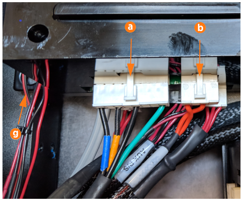
Generation 2, attached with nut (a): Use an 8 mm (5/16 in) nut driver to remove only the nut and the P-clip.
-
-
Remove the shielded holster cable from the opening in the P-clip (b).
-
Remove the existing extrusion from the station.

Remove the Contactor Assembly
Before work, take a picture of which cable tab plugs into which slot on the contactor assembly. Cables are color-coded (black is positive, red is negative). Color codes are different for each installed charge connector type. It is critical that the cables are reattached to their original locations.
-
Using a T20 Torx driver, remove the screws (a) that attach the cable tabs to the front of the contactor assembly.

-
Remove the cable tabs by moving them slightly back and forth while pulling straight out to release.
Avoid touching the tab contact area. Handle the cable tabs by their edges.There are up to three possible charge connector slots shown as 1, 2, and 3 on the front plastic cover (b). Note the position of each communication connector before removal. Each cable must be reattached to its original connector slot on the contactor assembly. Failure to do so may damage the station or vehicle. If the original connector location is unknown, the cable can be attached to the contactor assembly based on the connector type indicated by the label: CCS1/CCS2: #2 or #3 CHAdeMO: #1.
-
Remove all cables connected to the left side of the contactor assembly:
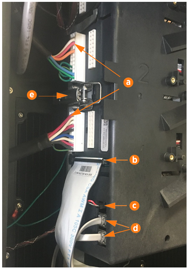
(a) Charge cable communications
(b) DCC
 Dispenser Charge Controller communication ribbon cable
(c) 24 V DC power
(d) CAN connectors
To remove the horizontal ribbon cable, push the tabs outward. Rock it gently from left to right as you pull out the cable.Each cable is keyed to its corresponding connector except the CAN cables, which are interchangeable.
-
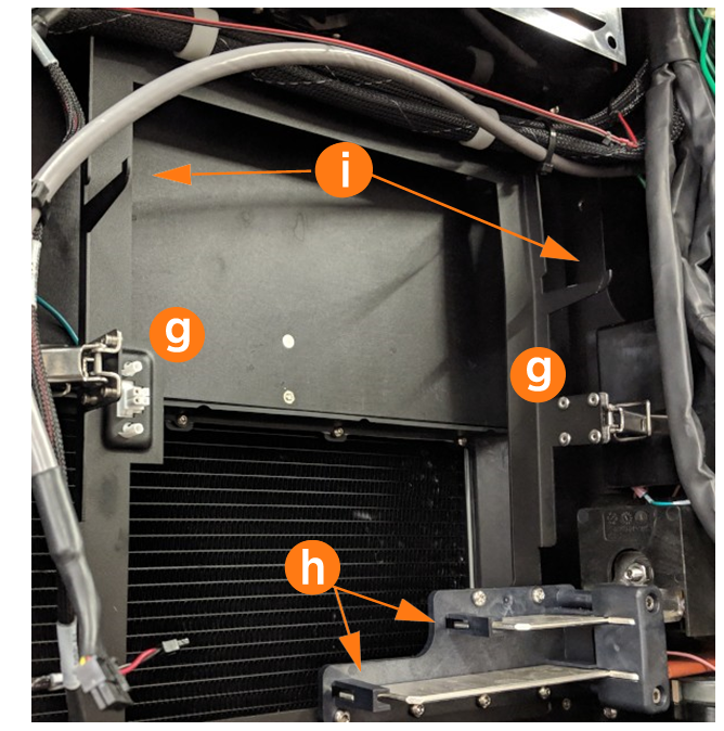
Open the securing latches (g) on the left and right sides of the contactor box assembly by pushing down on the lock tab and lifting the lever (e).
-
Disengage the contactor assembly from the large bus bar connections at the bottom (h) by holding it with two hands near the bottom and rocking the assembly slightly as you pull outward.
-
Once the bus bar connections release, pull the assembly forward along the support arms (i), then lift free from the station.
 Avoid touching the tab contact area. Handle the cable tabs by their edges.
There are up to three possible charge connector slots (shown as 1, 2, and 3 on the front plastic cover). Note the position of each communication connector before removal.
Remove the Auxiliary Power Supply
-
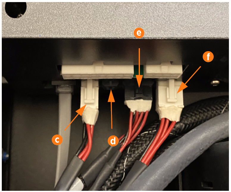
Disconnect the five connectors from the auxiliary power supply:
(a) 480 V power in
(b) Shunt trip relay connector
(c) CAN bus in
(d) Cooling I/O
(e) 12 V power out to internal components
(f) LED display 5 V
Use a T25 Torx driver to loosen the four screws at the corners of the auxiliary power supply. Do not fully remove screws: leave the screws in the charging station and move the power supply sideways to release it from the keyhole mounting tabs (g).
-
Slide the auxiliary power supply toward you to remove it.
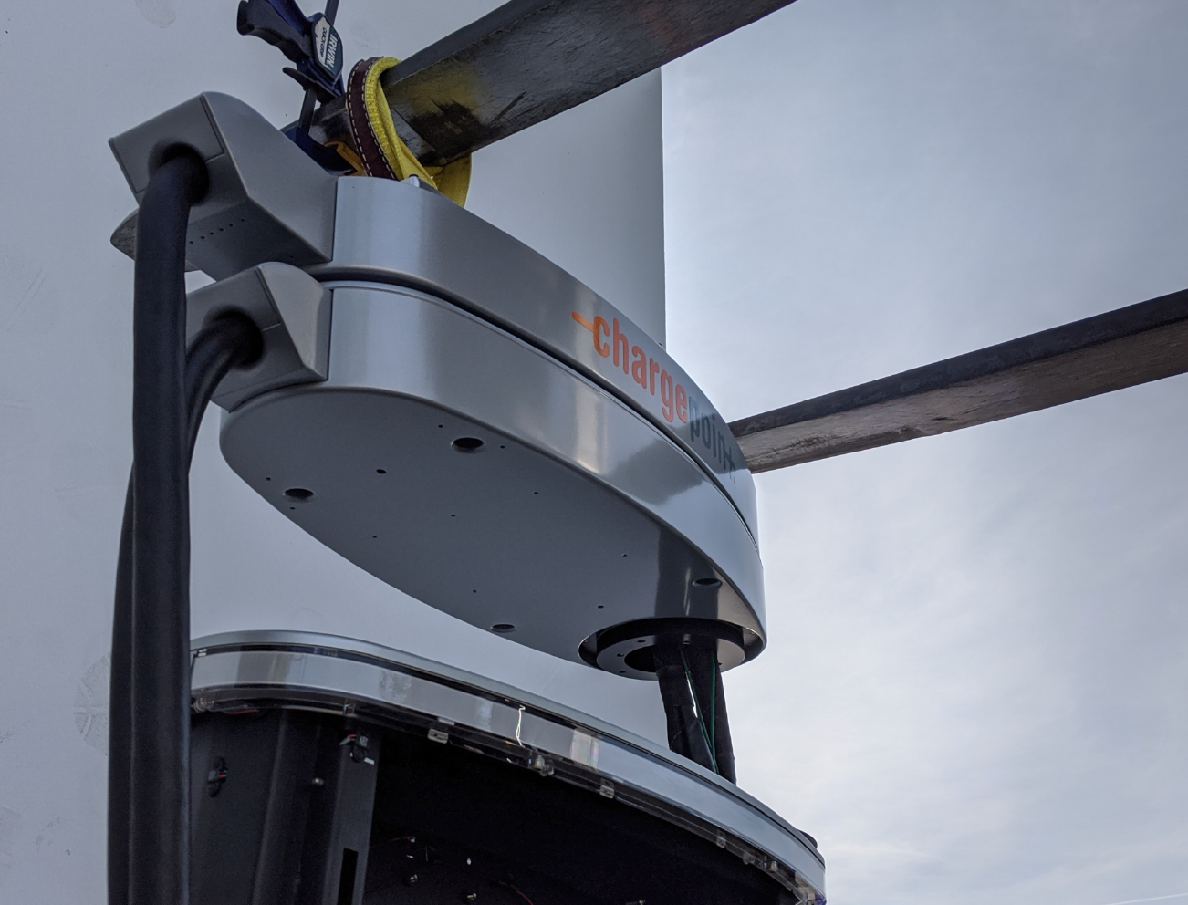
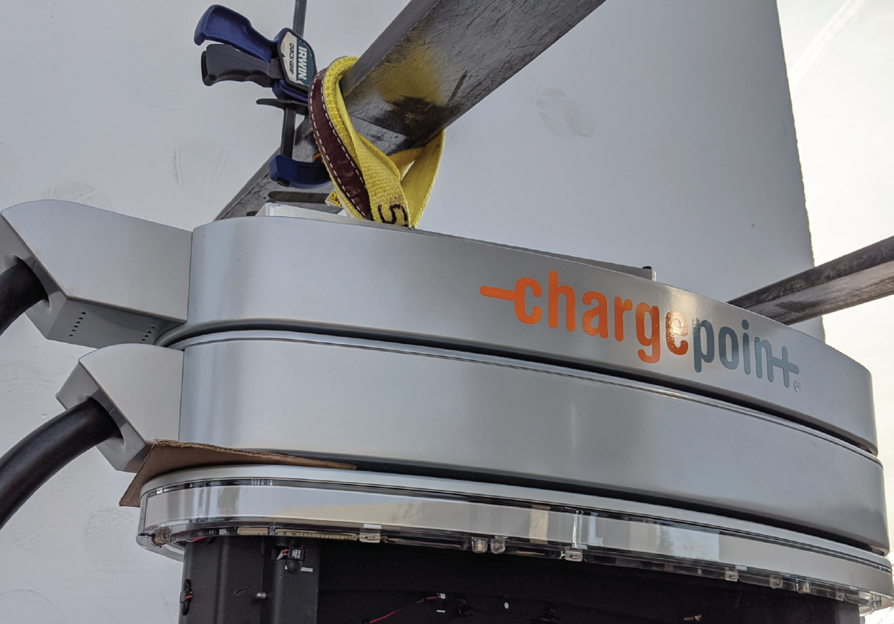
Remove the Swing Arm Assembly
-
Use an 10 mm (3/8 in) hex wrench to remove the two swing arm ground wires from the frame in the upper right corner.
-
Swing the top swing arm open and use cardboard or other non-scratching material to shim it in place. Use a T25 Torx to loosen the four M5 captive screws that hold the top lid to the station from below. Set the top lid aside on a padded surface.
-
Using a step ladder, use a T25 Torx to remove the second and fourth screws from the left, along both the front and back edges (four screws total).


-
Loop the lifting strap through the top ring of the lifting plate so that all loops can be picked up by a forklift fork.
-
Use a T25 to attach the lifting plate to the left side of the swing arm assembly. Hand tighten all four screws.
-
As a safety measure, position the forklift to secure the lifting plate straps. Ensure the straps are secured at least 300 mm (12 in) from the end of the fork.
-
Secure a C-clamp on the outside of the strap to secure it to the fork.
-
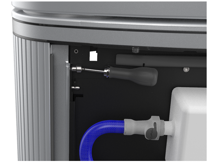
Use foam, a shop cloth, or other non-damaging object to block the hole in the right side of the frame and prevent screws from dropping into the station (white foam shown).
-
Remove the toroid ferrite from each pair of charge cables.
When reinstalling, the narrow part of the sleeve faces downward. -
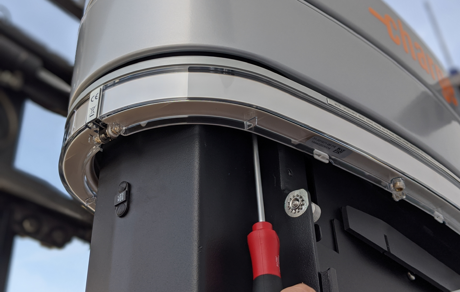
Use a T25 Security Torx to remove one external screw next to the right extrusion, under the edge of the LED diffuser.
-
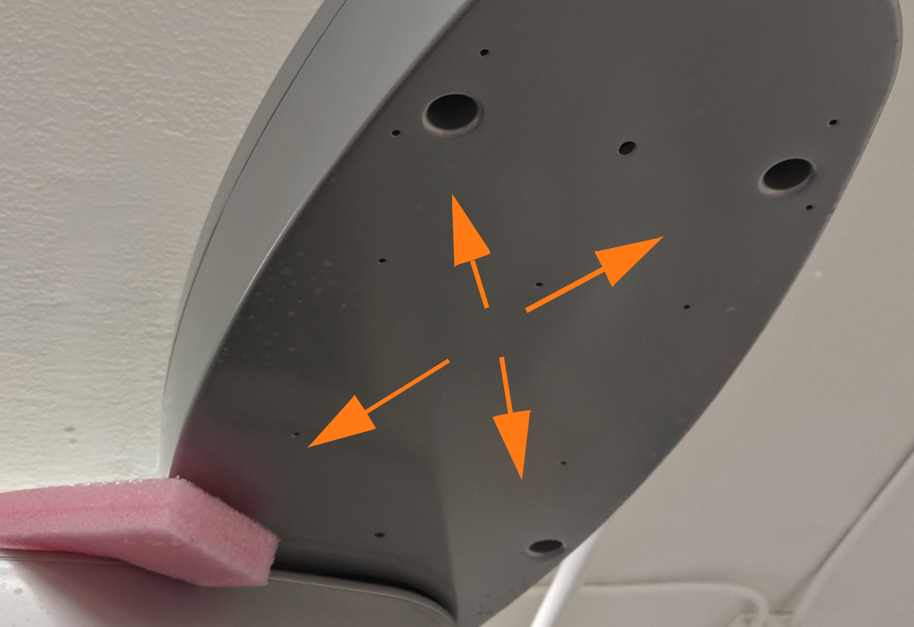
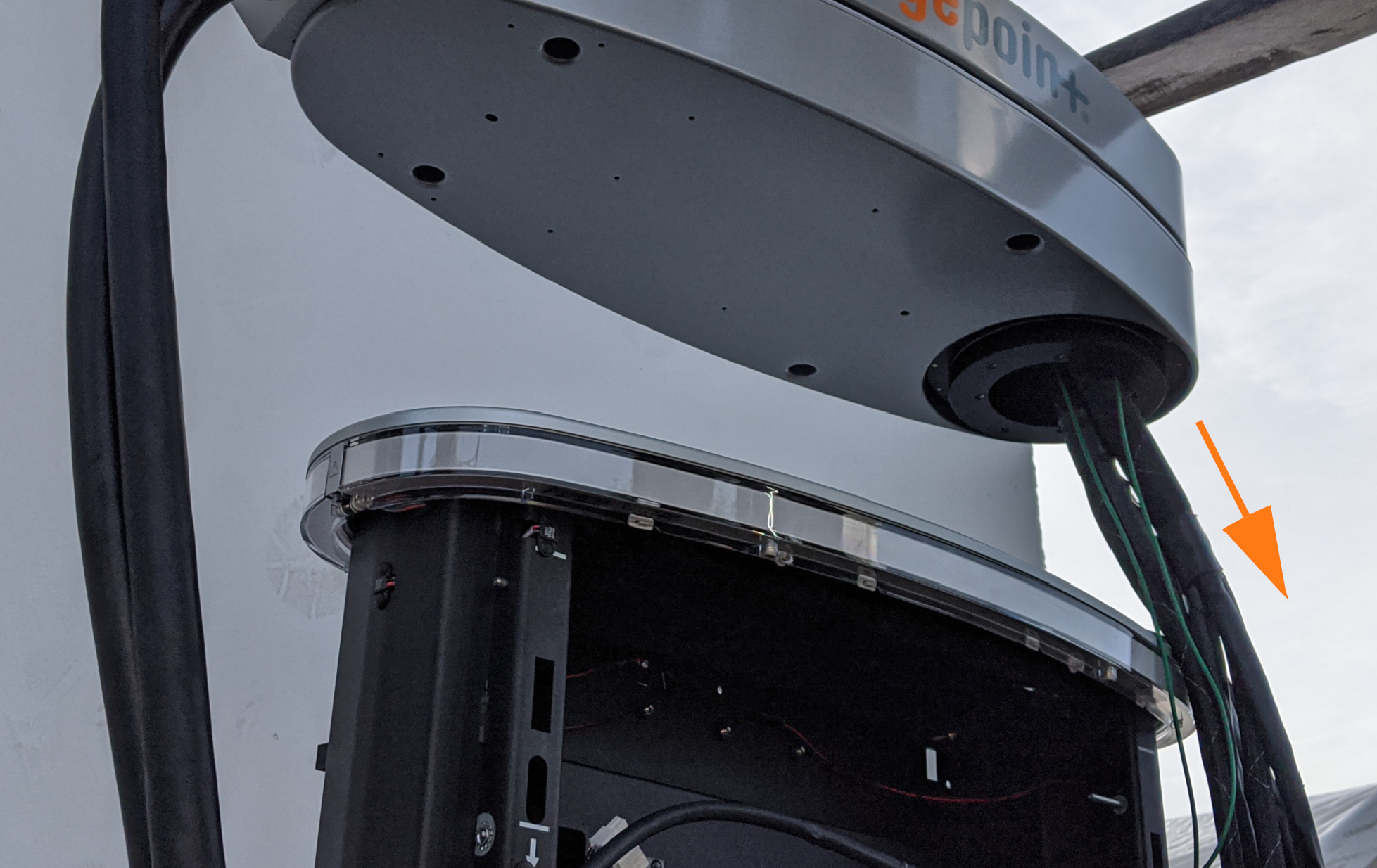
Use a T25 Security Torx to remove six screws from the circular housing under the swing arm ((a), three of the six screws shown). Bundle the cables and move them to the left to access the back screws. Save the screws for later re-use.
Do not remove the two screws that hold the gasket to the frame (b). The gasket screws look different because they are not recessed into the gasket.Do not drop any screws into the station. Fasteners can drop into the bus bars and cause electrical malfunction or damage.
-
Position one person to the side, holding the bundle of cables. Slowly lift the forklift forks a minimum of 254 m (10 in) above the frame.
-
Have the person on the ground carefully feed the conductor, communication cables, and ground wires up through the station’s circular bushing opening while the forklift continues to lift the swing arm assembly free of the station.
-
Set the old swing arm assembly and its cables aside for later re-packaging in the FRU
Field Replaceable Unit kit crate. -
Transfer the lifting plate from the old swing arm assembly to the new one. Hand tighten all four screws.


Replace the Swing Arm Assembly
-
Use the forklift to position the new swing arm assembly a minimum of 254 mm (10 in) above the station.
-
While the assembly is suspended, carefully feed the conductors, communication cables, and ground wires down through the top of the station into the circular bushing opening.
-
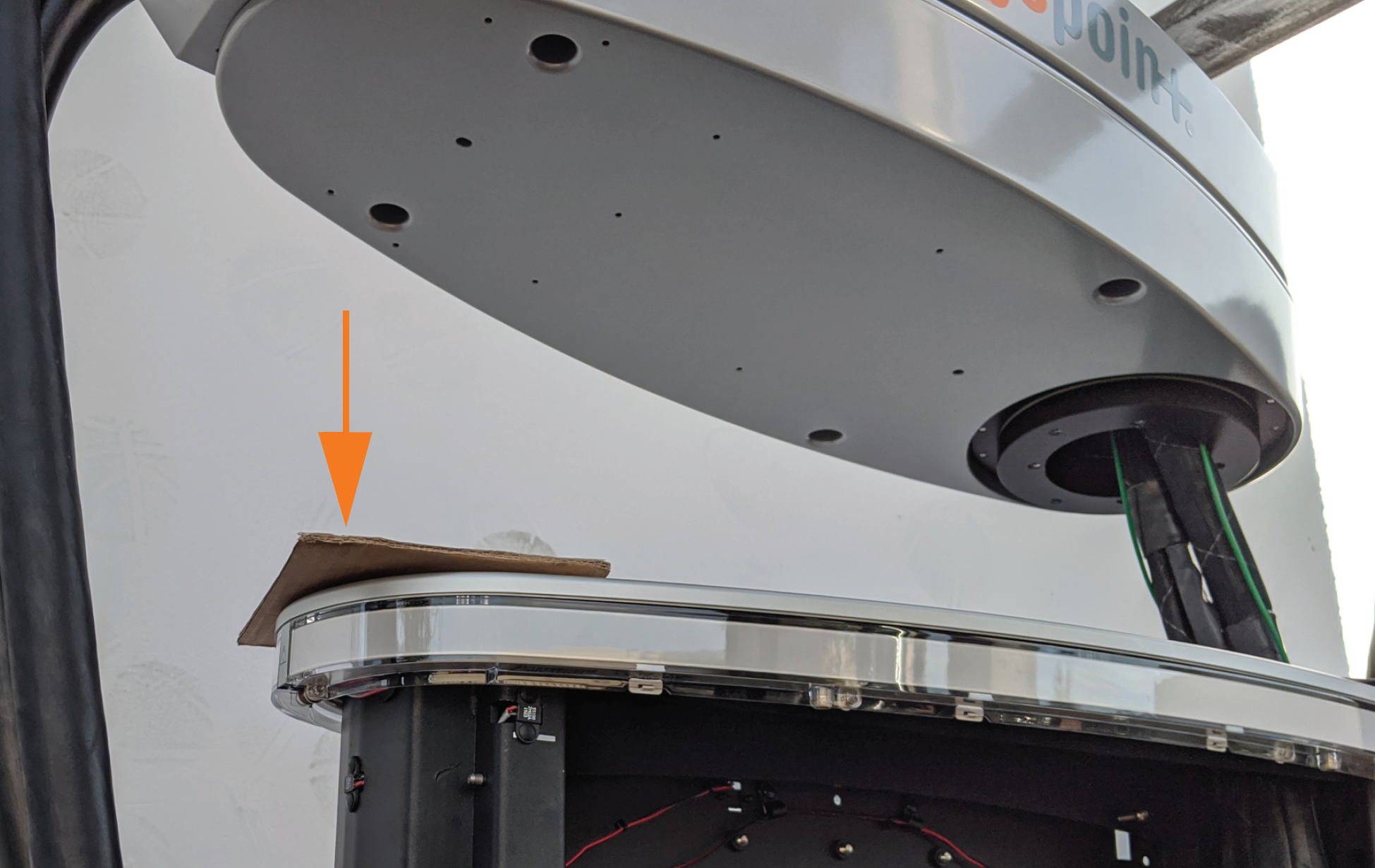
Position a piece of thin cardboard as a shim on the left side of the frame’s top skid pad to help level the swing arms.
-
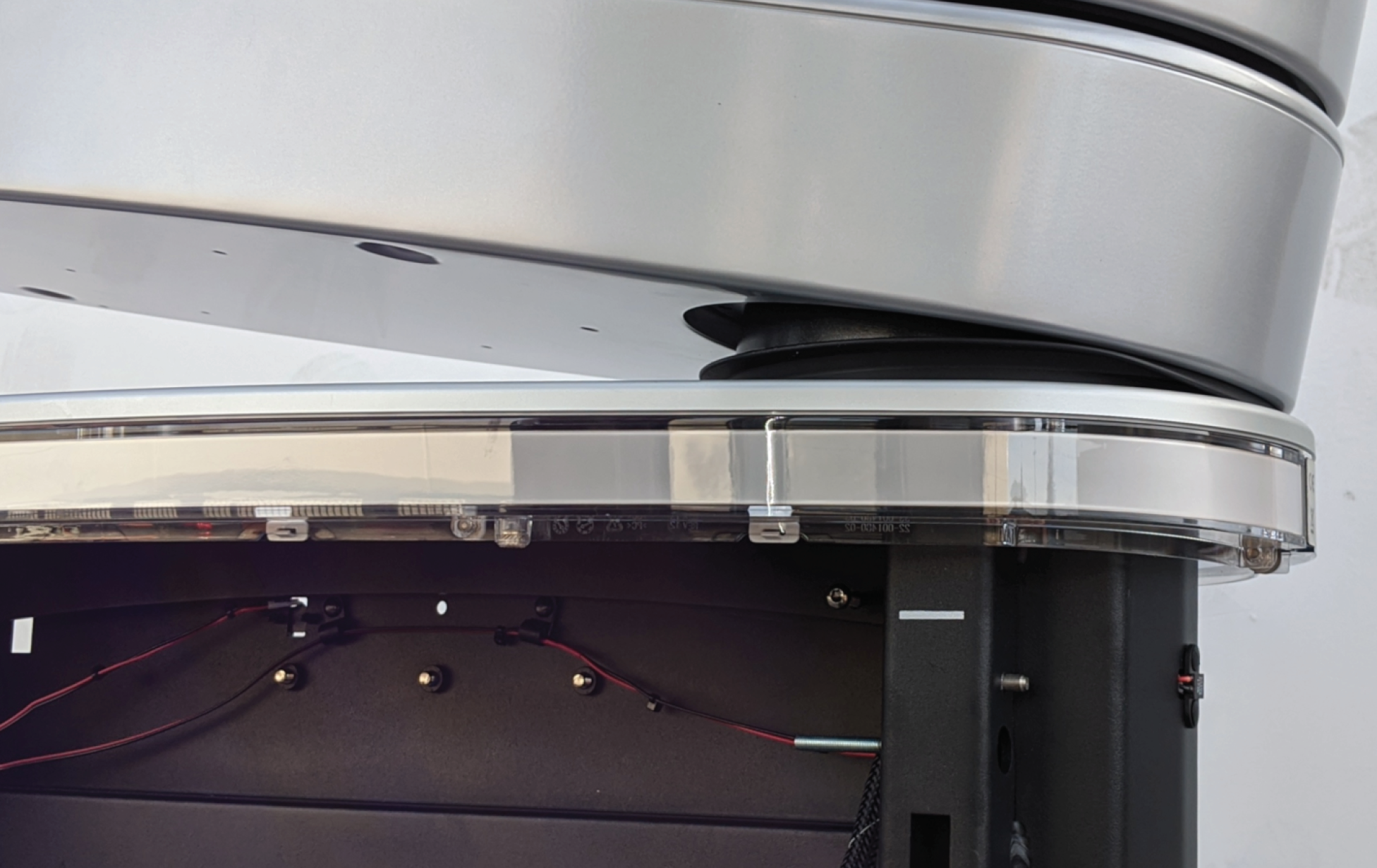
Align the right side of the swing arm so that the circular housing fits inside the bushing.
-
Use the forklift to slowly lower the swing arm assembly into place. Do not remove the forklift yet.
-
Use a T25 Security Torx to replace the one external screw next to the right extrusion. Torque to 4.5 Nm (40 in-lb).
Do not drop any screws into the station. Fasteners can drop into the station bus bars and cause electrical malfunction or damage. Account for all fasteners before completing the procedure. -
Use a T25 Security Torx to replace the six screws into the circular housing under the swing arm: the three bushing screws on the left (interior side) of the cables first, then the three screws on the right (exterior side) of the cables. Torque to 4.5 Nm (40 in-lb).
-
Remove the C-clamp and the forklift.
-
Use an 10 mm (3/8 in) hex wrench to reattach the swing arm ground wires to the frame in the upper right corner, both on same stud. Torque to 2.9 Nm (25 in-lb).
-
Remove the lifting plate. Attach it to the old swing arm that is being returned to ChargePoint.
-
Replace the top swing arm plate per previous instructions. Torque to 2.9 Nm (25 in-lb).
-
Replace the ferrites on each pair of charge cable conductors.

Replace the Contactor Assembly
-
Ensure latch clasps are open and not blocking the contactor assembly before installation.
-
Rest the alignment pegs of the contactor assembly on the support arm hooks.
-
Slide the contactor assembly back along the support arms. Push the assembly to engage the bus bars until fully seated.
Ensure the connectors are aligned before pressing in. Do not apply excessive force. Doing so can damage the connectors. Once seated, gently pull the contactor assembly outward as a push-pull test to confirm it is securely seated.
Ensure all cables are accessible without being pinched or caught under the contactor assembly. -
Fasten the latches on the right and left sides of the contactor assembly.
-
Reconnect each cable on the left side of the contactor assembly.
-
Wipe down the contact surface of each cable tab with isopropyl alcohol wipes.
-
After double-checking the photo of the cable order, push each cable tab into its corresponding slot. Ensure the plastic guide post is fully seated to be level with the surface of the cable tab.
-
Use a T20 Torx driver to re-fasten the screw (a) on each cable tab. Torque to 2.8 Nm (25 in-lb).
-
Tuck the excess contactor cable down the side of the enclosure to avoid interfering with the cover panel in a later step.
(a) Charge cable communications
(b) DCC
Dispenser Charge Controller communication ribbonEnsure the key aligns with the notch in the socket.(c) 24 V DC power
(d) CAN connectors (interchangeable)
Secure connector body to the mating connector on the contactor assembly and ensure the tabs are in the open position. During connection the insertion tabs will automatically close onto the connector housing.
-
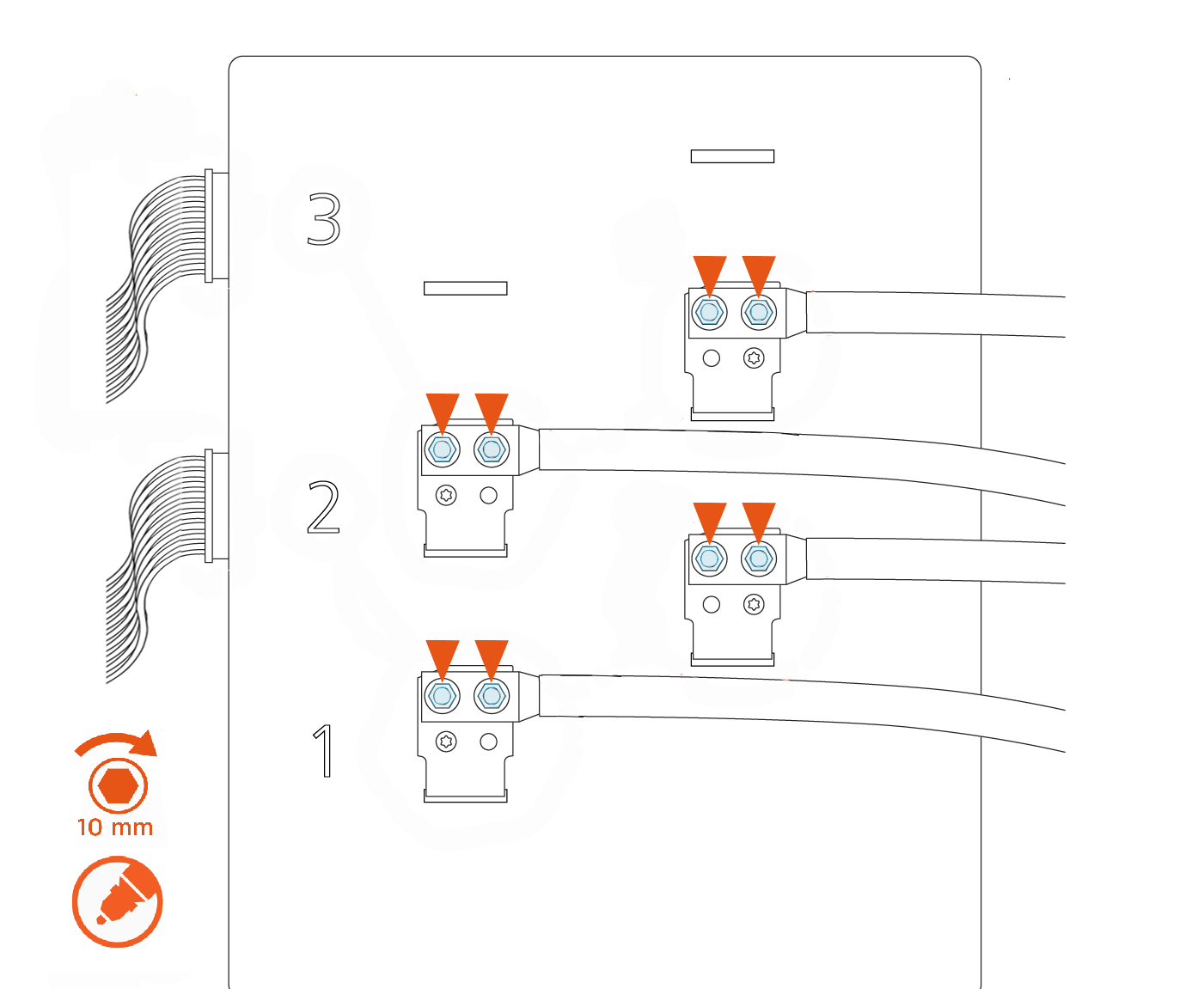
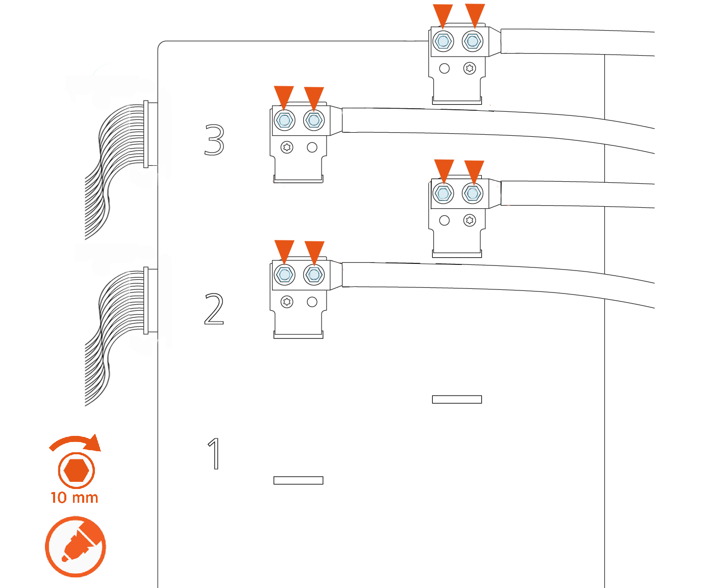
Use a calibrated torque wrench with a 10 mm (3/8 in) socket to retorque the nuts on all lugs of the contactor assembly to 6.8 Nm (60 in-lb), as shown in the images below. Mark the nuts with a paint pen.
There are up to three possible charge connector slots shown as 1, 2, and 3 on the front plastic cover of the contactor assembly.See the following examples of 2-relay and 3-relay connector boxes for reference:
Example: 2-relay contactor box
Example: 3-relay contactor box
Replace the Auxiliary Power Supply
-
Slide the auxiliary power supply into the station above the contactor assembly.
-
Ensure the keyhole mounting tabs at the corners of the auxiliary power supply are aligned with the loose screws on the station. Torque the screws hand-tight.
-
Connect the five connectors from the auxiliary power supply:
-
480 V power in
-
Shunt trip relay connector
-
CAN bus in
-
Cooling I/O
-
12 V power out to internal components
-
LED display 5 V
-
Replace the Right Extrusion
-
Slightly tilt the right extrusion and slide its top edge under the bottom edge of the area light bar. Align the holes in the extrusion with the guide pins on each side of the Express 250’s frame. This temporarily holds the extrusion in place.
-
Install the shielded holster cable and P-clip hardware to the extrusion holsters using either a T25 Torx Driver (Generation 1) or an 8 mm (5/16 in) nut driver (Generation 2).
-
Connect the longest cable to the bottom holster and the shortest cable to the top holster.
Ensure the connections are correctly seated, or the system will not operate. -
Using a step ladder, hold the extrusion with one hand and loosely secure the top two captive screws using the supplied T25 Torx driver.
The top and middle screws are asymmetrical. -
Use a T25 Torx driver to loosely secure the bottom two screws next. The Power Module holders must not be inside the charging station to have access to the bottom screws.
-
Use a T25 Torx driver to loosely secure the middle two screws, just above the Power Module mechanism. Access to the middle screws is easier with the Power Module mechanism handle in the closed (down) position.
-
Tighten all right extrusion screws.
-
At the bottom right of the Express 250, press and hold the yellow release latch while pushing the Power Module tray into the station until it locks into place.
-
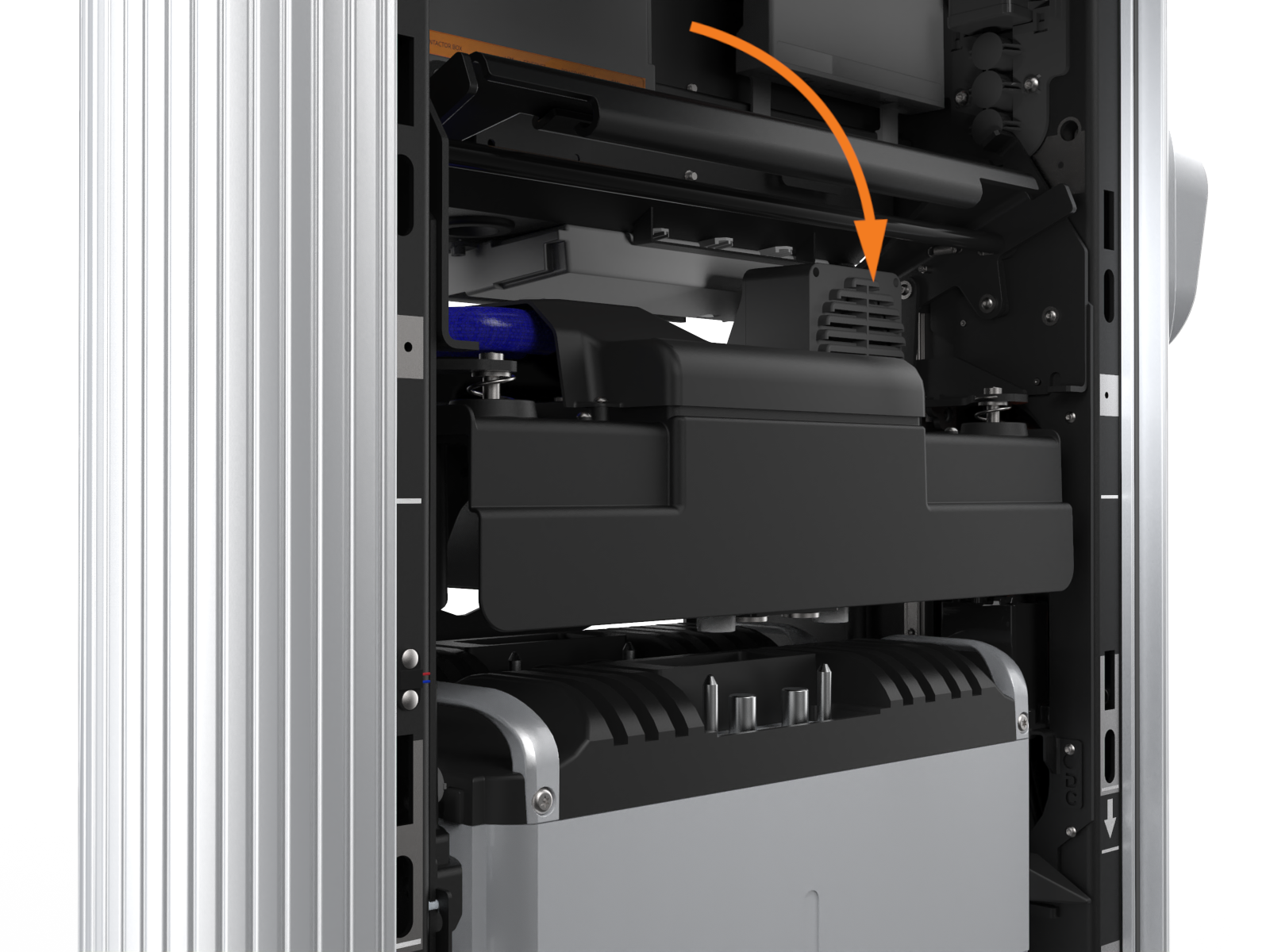
Using two hands, squeeze the Power Module mechanism’s release bar and lower it halfway to check alignment with the ports and guide posts.
-
Lower the Power Module mechanism until you hear a click as the mechanism locks into place. Ensure the mechanism is fully engaged with all Power Module connectors. The Power Module mechanism should fully cover the ridges on the Power Module’s top edge.


If the mechanism does not engage, raise it again and push the Power Modules to the back of the station to realign, then try again. Do not apply excessive force.
REVERSE THE ABOVE STEPS TO REPLACE THE EMI![]() Electromagnetic Interference SHIELD (IF APPLICABLE), REAR PANELS, FRONT PANELS, LED DISPLAY, AND AREA LIGHT BAR.
Electromagnetic Interference SHIELD (IF APPLICABLE), REAR PANELS, FRONT PANELS, LED DISPLAY, AND AREA LIGHT BAR.
