Replace the Fan Tray Assembly

To replace the fan tray assembly, complete the following steps:

Required Tools and Materials

  • ChargePoint replacement part #CPE250-FANTRAY-F

  • #2 Phillips screwdriver

  • T25 Security Torx driver

  • Step ladder

  • Headlamp

About Panels

All panels have guide tabs that align with corresponding slots on the product’s frame. When removing a panel, lift the panel upward to release these tabs from their slots.

When installing a panel, align these tabs above their corresponding slots and press the panel downward.

Power Off the Station

Power off at the breaker panel and lock out/tag out before continuing work.

RISK OF SHOCK. Before performing this procedure, disconnect the power to the station at the service panel. Keep power off for this circuit until all cover panels are correctly reinstalled and the work scope is completed. FAILURE TO FOLLOW THESE INSTRUCTIONS CAN RESULT IN SERIOUS INJURY OR LOSS OF LIFE.

Remove the Top Rear Panel

  1. Using a T25 Torx (or a Phillips #2 screwdriver for early charging stations), loosen the two hidden captive screws located in the top rear panel’s vents, inset from each bottom corner.

  2. Using a T25 Torx driver, loosen the two captive screws located at the top of the top rear panel. Using two hands, hold the top rear cover at an angle to remove, leading with the bottom edge.

    When reinstalling, squeeze the sides of the panel inward to fit the tabs into place in the C-channel, inside the watertight gasket.

Remove the Fan Tray Assembly

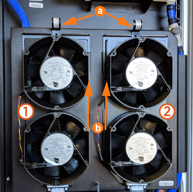
Fan Tray Assemblies are arranged in two banks: Left Bank (1) and Right Bank (2). When the fan banks are opened from the rear for access, the Left Bank is positioned on the left-hand side and the Right Bank on the right-hand side of the fan.

If an Express 250 station reports either or both of the following Cooling Fan Faults (1001 or 1002), the NOSClosed Network Operating System Diagnostics tab for that station will display:

  • Fan Fault Left Bank: A fan in the left bank is stuck

  • Fan Fault Right Bank: A fan in the right bank is stuck

Follow the below steps to remove the Fan Tray Assembly:

  1. The system has two fan trays (left and right). On the fan tray to be replaced, pull the tab (a) at the top of the fan tray assembly forward to disengage it.

  2. Zip ties on the fan tray must be cut off to remove the fan tray assembly.

  3. Using two hands, slide the tray upward until the mounting tabs (b) on the fan tray assembly are positioned above their corresponding slots.

  4. Check that the power connector at the base of the fan assembly easily disengages as the fan tray is lifted.

  5. Pull the fan tray assembly toward you to remove it.

Replace the Fan Tray Assembly

When replacing the fan tray:

  • Ensure all four tabs on the fan tray assembly are positioned above their corresponding slots.

  • Press the fan tray assembly against the Express 250, then slide the fan tray downward.

  • Ensure each tab on the fan tray is located under, and not over, its corresponding slot.

  • Ensure the top tabs are engaged into the metal housing behind them.

  • Ensure the fan’s power connector at the bottom seats correctly.

Fan tray zip ties do not need to be replaced.

REVERSE THE ABOVE STEPS TO REPLACE THE TOP REAR PANEL.

Power On the Station

Once all cover panels are installed, power on the station. The on-screen Installation Wizard steps you through any required tasks to set up the station and verify that it can operate properly.

An Installation Wizard test checks that all cover panels are correctly installed and fully seated. Check the lower right corner of the screen for any error messages. If panel errors appear, match the panel letters to this illustration.

Labeled diagram of product, tools or parts.

(a) Front bottom panel

(b) Middle vent panel

(c) Front top panel

(d) LED display

(e) Area light bar

(f) Rear bottom panel

(g) Rear middle panel

(h) Rear top panel

(i) Left extrusion

(j) Right extrusion

RISK OF SHOCK. If a fault exists, turn the power off at the service panel to BOTH product paired charging stations during work and keep it off until all panels are reinstalled. Internal components can present a shock hazard. FAILURE TO FOLLOW THESE INSTRUCTIONS CAN RESULT IN SERIOUS INJURY OR LOSS OF LIFE.

If any panel needs re-installation, review the procedures above to double-check that all panels are fully seated and that the edges of all signs are captured fully by the panels around them. For further details, refer to Introduction.