Introduction
Follow this guide to service and replace the Express 250 components.
Before You Begin
RISK OF SHOCK. Some stations share DC power (“paired” configuration). Pairing should be marked on the AC disconnect or breaker panel. Before performing this procedure, check for pairing and, if present, disconnect the power to BOTH stations at the service panel.
Whether Standalone or Paired, follow standard practice and local code to de-energize the applicable circuit and lock out/tag out the disconnect before proceeding.
Use a multimeter to test that power is off. Keep power off for this circuit until all cover panels are correctly reinstalled and the work scope is completed. FAILURE TO FOLLOW THESE INSTRUCTIONS CAN RESULT IN SERIOUS INJURY OR LOSS OF LIFE.
- Use tools suitable to torque metric fasteners. All fasteners used are in metric sizes.
- Use the given torque values to tighten the fasteners.
- Ensure that the tools such as torque tool, multimeter, and Ethernet tester are calibrated.
- If the charging station is not installed, commissioned, or serviced by a ChargePoint certified technician using a ChargePoint-approved method, it is excluded from all ChargePoint and other warranties and ChargePoint is not responsible.
- You must be a licensed electrician and complete training at https://www.chargepoint.com/partners/training-certification to become ChargePoint certified and to access ChargePoint's web-based installer tools or ChargePoint Installer app.
When removing a part, avoid damage to part by setting it gently on a padded surface.
Additional Documentation
For your safety and the safety of others, complete these steps before you begin:
-
Familiarize yourself with the instructions in the Service Guide.
-
If you have not installed or serviced the Express 250 recently, orient yourself by reviewing the Site Design, Installation, and Datasheet, as well as any other materials you find helpful.
Access ChargePoint documents at ChargePoint Product Reference Documentation.
|
Document |
Content |
Primary Audiences |
|
Datasheet |
Full station specifications |
Site designer, installer, and station owner |
|
Site Design Guide |
Civil, mechanical, and electrical guidelines to scope and construct the site |
Site designer or engineer of record |
|
Concrete Mounting Template Guide |
Instructions to embed the charging station template in a concrete pad with anchor bolts and conduit placement (these may also be included in the Site Design Guide) |
Site construction contractor |
|
Surface Conduit Entry Kit Guide |
Instructions for sites where conduit cannot be run underground |
Installer |
|
Construction Signoff Form |
Checklists used by contractors to ensure the site is correctly completed and ready for product installation |
Site construction contractor |
|
Installation Guide |
Anchoring, wiring, and powering on |
Installer |
|
Operation and Maintenance Guide |
Operation and preventive maintenance information |
Station owner, facility manager, and technician |
|
Service Guide |
Component replacement procedures, including optional components |
Service technician |
|
Declaration of Conformity |
Statement of conformity with directives |
Purchasers and public |
Check and Protect Parts
To ensure your safety, do the following:
-
Use only authorized parts and accessories sold and supplied by ChargePoint for the unit and model.
-
Keep components in original packaging, free of moisture, and protected from damage until you install or service them at the site.
-
Store all shipments of components in a dry covered location and protect from moisture.
-
Familiarize yourself with the contents of each shipping box.
-
Ensure that you have all the parts for the work you plan to perform.
-
Have more than one technician or qualified support person present if components are heavy.
-
Keep liquids and objects containing liquid away from the unit, never on or inside.
If Damaged, Do Not Service
Do not perform work or remove any signs or covers from the unit if you find any of the following:
-
The charging station housing shows mechanical damage.
-
The charging cables or connectors are visibly damaged.
-
The station is unstable or moves.
If you find such damage, turn off the station, advise the site manager to keep the unit(s) off, and contact ChargePoint immediately. Find your region’s technical support number at chargepoint.com/support.
Field Replacement Unit
This topic shows the names and locations of all Field Replaceable Units (FRUs) on the Express 250 charging station that can be serviced in the field by a trained and approved third party.
FRU Service Policies
These notes and cautions apply to any field service procedure for the Express 250 Charging Station.
RISK OF SHOCK. Some stations share DC power (paired configuration). Pairing should be marked on the AC disconnect or breaker panel. Before performing this procedure, check for pairing and, if present, disconnect the power to BOTH stations at the service panel. Whether Standalone or Paired, follow standard practice and local code to de-energize the applicable circuit and lock out/tag out the disconnect before proceeding. Use a multimeter to test that power is off. Keep power off for this circuit until all cover panels are correctly reinstalled and the work scope is completed. FAILURE TO FOLLOW THESE INSTRUCTIONS CAN RESULT IN SERIOUS INJURY OR LOSS OF LIFE.
- If the charging station is not installed, commissioned, or serviced by a ChargePoint certified technician using a ChargePoint-approved method, it is excluded from all ChargePoint and other warranties and ChargePoint is not responsible.
- You must be a licensed electrician and complete training at https://www.chargepoint.com/partners/training-certification to become ChargePoint certified and to access ChargePoint's web-based installer tools or ChargePoint Installer app.
Product Disposal
![]() Applicable to NA - Do not dispose of as part of unsorted domestic waste. Inquire with local authorities regarding proper disposal. Product materials are recyclable as marked.
Applicable to NA - Do not dispose of as part of unsorted domestic waste. Inquire with local authorities regarding proper disposal. Product materials are recyclable as marked.
![]() Applicable to EU - To comply with Directive 2012/19/EU of the European Parliament and of the Council of 4 July 2012 on waste electrical and electronic equipment (WEEE), devices marked with this symbol may not be disposed of as part of unsorted domestic waste inside the European Union. Enquire with local authorities regarding proper disposal. Product materials are recyclable as marked.
Applicable to EU - To comply with Directive 2012/19/EU of the European Parliament and of the Council of 4 July 2012 on waste electrical and electronic equipment (WEEE), devices marked with this symbol may not be disposed of as part of unsorted domestic waste inside the European Union. Enquire with local authorities regarding proper disposal. Product materials are recyclable as marked.
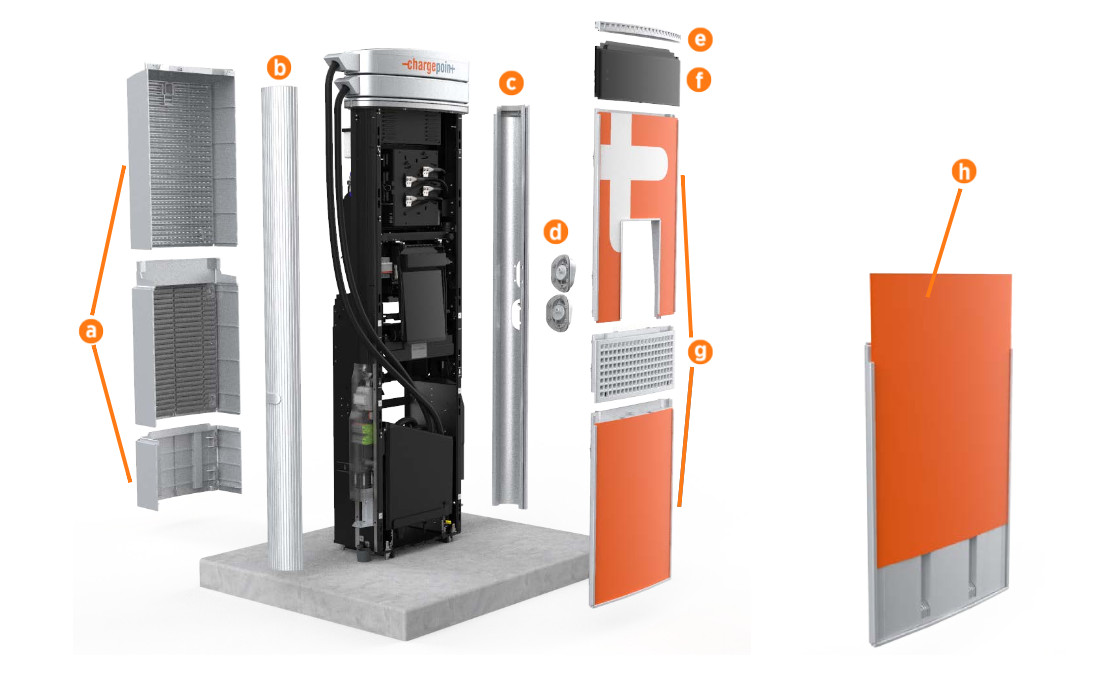
Cover Panels
|
Part |
Product Name |
|---|---|
|
a Rear panels (3) |
CPE250-REAR-LWR-PANELS-F CPE250-REAR-UPR-PANELS-F CPE250-REAR-MID |
|
CPE250-SIDEPANEL-LH-F |
|
|
c Right extrusion (available in single or dual cable) |
CPE250-SIDEPANEL-RH1-F CPE250-SIDEPANEL-RH2-F |
|
d Holsters (available in CCS1, CCS2, and CHAdeMO) |
CPE250-HOLS-CCS1-F CPE250-HOLS-CCS2-F CPE250-HOLS-CHD-F |
|
CPE250-AREALIGHT-F |
|
|
CPE250-LEDDISPLAY-F |
|
|
g Front panels (3) |
CPE250-FRONT-LWR-PANELS-F CPE250-FRONT-VENT-PANELS-F CPE250-FRONT-UPR-PANELS-F |
|
h Signs (inserts for cover panels) |
CPE250-DEFAULT-SIGNAGE Custom signs available: name varies |
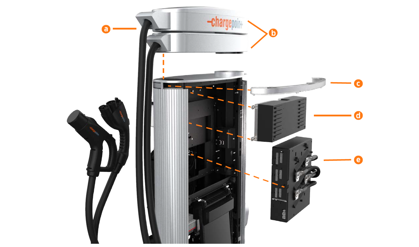
Front Access, Top
|
Part |
Product Name |
|---|---|
|
CHAdeMO available in 125 A (CE marked) and 140 A (UL Listed). CCS1 (UL Listed) available in 174 A and 200 A CCS2 (CE marked) available in 200 A. Contact ChargePoint if you are unsure what amperage your station uses. |
CPE250-CABLE-CHD-125A-F CPE250-CABLE-CHD-140A-F CPE250-CABLE-CCS1-174A-F CPE250-CABLE-CCS1-200A-F CPE250-CABLE-CCS2-200A-F |
|
Available in single or dual cable. Dual cable available in CCS1/CHAdeMO, CCS2/CHAdeMO, or CCS1/CCS2. |
CPE250-CABLE-CCS1-CHD-F CPE250-CABLE-CCS2-CHD-F CPE250-CABLE-CCS1-CCS2-F |
|
c LED diffuser, front |
CPE250-LEDBAR-FT-F |
|
CPE250-AUXPOWER-F |
|
|
CPE250-CONTACTBOX-F |
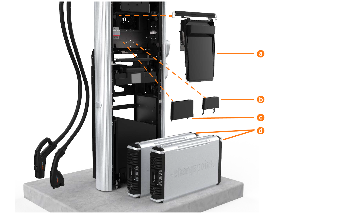
Front Access, Bottom
|
Part |
Product Name |
|---|---|
|
a Touchscreen (CPNK |
CPE250-CCOM CPE250-CCOM |
|
b I/O Expander, mounted on rail behind touchscreen |
CPE250-IOEXPANDER-F |
|
c Station Management Unit (DCC |
CPE250-DCC |
|
d Power Modules (ship separately from charging station) |
System-PM |
Rear Access
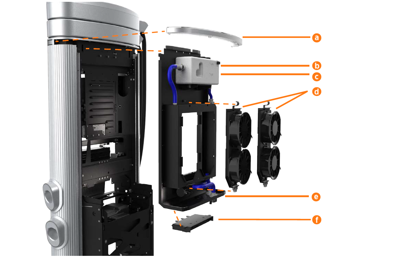
|
Part |
Product Name |
|---|---|
|
a LED diffuser, rear |
CPE250-LEDBAR-RR-F |
|
b Coolant (jug for refills) |
CPE250-COOLANT-F |
|
CPE250-RESERVOIR-F |
|
|
CPE250-FANTRAY-F |
|
|
e Heat exchanger assembly (behind fan trays) |
CPE250-HEATEX-F |
|
CPE250-COOLING-CTRLR-F |
Protective Guards and Tools
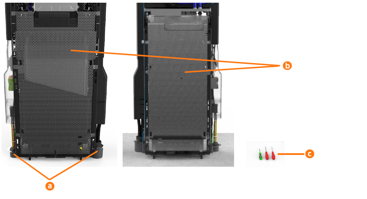
|
Part |
Product Name |
|---|---|
|
a Rodent guard brackets, left and right (2) |
CPE250-RODENT-GUARD-F |
|
b EMI |
CPE250-EMISHIELDS-F |
|
c Tool kit (Torx and Wago drivers) |
CPE250-TOOLKIT-F |
