Replace a Holster
To replace a holster, complete the steps in this chapter.
Required Tools and Materials
|
|
Head lamp |
|
T10, T20 and T25 Torx security screwdriver |
|
|
Flat head screwdriver |
|
8 mm (5/16 mm) nut Torque screwdriver |
|
|
ChargePoint replacement part for your charging connector type: CCS1, CCS2, CHAdeMO, or NACS |
|
#2 Phillips screwdriver |
Before you Begin
Complete the following procedures:
Replace the Holster
-
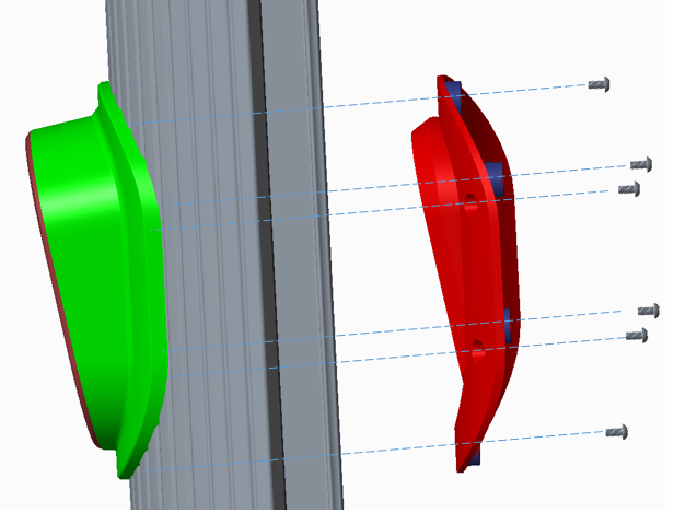
Lay the right extrusion down on a protected surface, with the inside facing up.

-
Use a T20 Torx to remove the six holster housing screws from the holster backing (a). Set them aside for reuse.
-
Use a T10 Torx to remove the four holster body screws from the holster backing (b). Set them aside for reuse.
-
Remove the old holster backing from the inside of the extrusion.
-
Remove the old holster body and housing from the outside of the extrusion.
-
Position the new holster body and housing on the front of the extrusion together.
-
Install the new holster housing onto the extrusion and holster backing, using the six T20 screws.
-
Fasten the new holster body to the extrusion and backing, using the four T10 screws.
-
Re-connect the ground cable and LED board cable connector.
Replace the Right Extrusion
-
Slightly tilt the right extrusion and slide its top edge under the bottom edge of the area light bar. Align the holes in the extrusion with the guide pins on each side of the Express 250’s frame. This temporarily holds the extrusion in place.
-
Install the shielded holster cable and P-clip hardware to the extrusion holsters using either a T25 Torx Driver (Generation 1) or an 8 mm (5/16 in) nut driver (Generation 2).
-
Connect the longest cable to the bottom holster and the shortest cable to the top holster.
Ensure the connections are correctly seated, or the system will not operate. -
Using a step ladder, hold the extrusion with one hand and loosely secure the top two captive screws using the supplied T25 Torx driver.
The top and middle screws are asymmetrical. -
Use a T25 Torx driver to loosely secure the bottom two screws next. The Power Module holders must not be inside the charging station to have access to the bottom screws.
-
Use a T25 Torx driver to loosely secure the middle two screws, just above the Power Module mechanism. Access to the middle screws is easier with the Power Module mechanism handle in the closed (down) position.
-
Tighten all right extrusion screws.
-
At the bottom right of the Express 250, press and hold the yellow release latch while pushing the Power Module tray into the station until it locks into place.
-
Using two hands, squeeze the Power Module mechanism’s release bar and lower it halfway to check alignment with the ports and guide posts.
-
Lower the Power Module mechanism until you hear a click as the mechanism locks into place. Ensure the mechanism is fully engaged with all Power Module connectors. The Power Module mechanism should fully cover the ridges on the Power Module’s top edge.

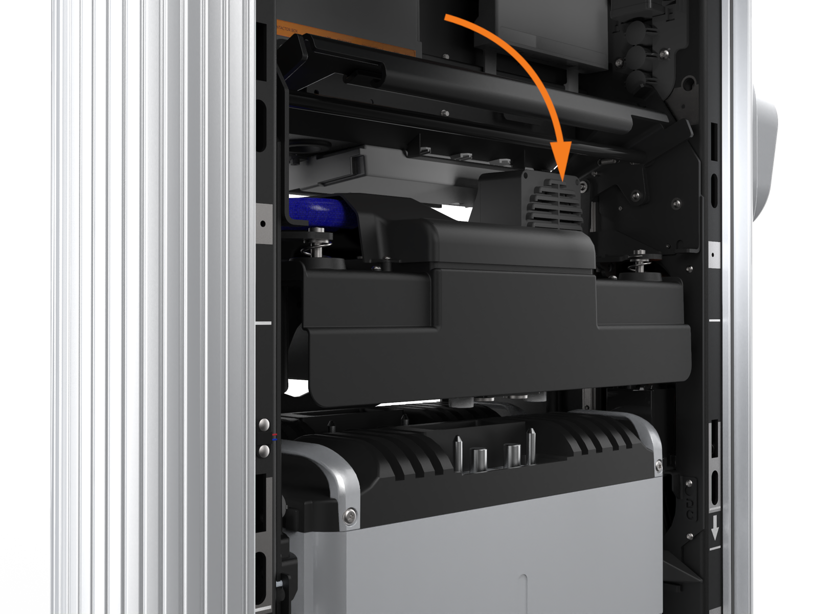

If the mechanism does not engage, raise it again and push the Power Modules to the back of the station to realign, then try again. Do not apply excessive force.
REVERSE THE ABOVE STEPS TO REPLACE THE EMI![]() Electromagnetic Interference SHIELD (IF APPLICABLE), REAR PANELS, FRONT PANELS, LED DISPLAY, AND AREA LIGHT BAR.
Electromagnetic Interference SHIELD (IF APPLICABLE), REAR PANELS, FRONT PANELS, LED DISPLAY, AND AREA LIGHT BAR.
