Replace Coolant Reservoir
To replace the coolant reservoir, complete the following steps:
Required Tools and Materials
-
ChargePoint replacement part CPE250-RESERVOIR-F
-
ChargePoint replacement part CPE250-COOLANT-F
-
#2 Phillips screwdriver
-
T25 Security Torx driver
-
T27 Security Torx driver
-
Headlamp
-
Lock out/tag out equipment
-
Safety glasses
-
Funnel
-
5-6 lint-free absorbent cloths
-
Step ladder
About Panels
All panels have guide tabs that align with corresponding slots on the product’s frame. When removing a panel, lift the panel upward to release these tabs from their slots.
Power Off the Station
Power off at the breaker panel and lock out/tag out before continuing work.
RISK OF SHOCK. Before performing this procedure, disconnect the power to the station at the service panel. Keep power off for this circuit until all cover panels are correctly reinstalled and the work scope is completed. FAILURE TO FOLLOW THESE INSTRUCTIONS CAN RESULT IN SERIOUS INJURY OR LOSS OF LIFE.
Remove the Top Rear Panel
-
Using a T25 Torx (or a Phillips #2 screwdriver for early charging stations), loosen the two hidden captive screws located in the top rear panel’s vents, inset from each bottom corner.
-
Using a T25 Torx driver, loosen the two captive screws located at the top of the top rear panel. Using two hands, hold the top rear cover at an angle to remove, leading with the bottom edge.
When reinstalling, squeeze the sides of the panel inward to fit the tabs into place in the C-channel, inside the watertight gasket.
Replace the Reservoir
-
Using absorbent cloths to guard against coolant spills, disconnect the two quick disconnect valves found on either side of the coolant reservoir (a) and (b).
-
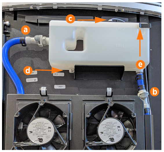
Using absorbent cloths to guard against coolant spills, unscrew the level sensor cap (c) from the top of the reservoir. Dry the sensor line components and set them gently aside for later reinstallation.
-
Use a Torx T27 driver to remove the bottom reservoir screw (d). Keep the screw for later reinstallation.
-
Gently slide the coolant reservoir to the left and up, to release it from the right side bracket (e) and its shelf.
-
Place the new reservoir on the shelf and slide it to the right and down until it is seated in the bracket.
-
Use a Torx T27 driver to fasten the bottom reservoir screw. Torque to 0.6 Nm (5 in-lb).
-
Reinstall the level sensor line and fasten the top cap.
-
Connect both quick disconnects (a) and (b) on the sides. Hold a cloth around each valve and perform a push-pull test to ensure it is firmly seated.
-
Using a step ladder if needed, unscrew the reservoir cap (f). Use a funnel to fill the reservoir to the marked MAX line with coolant. Replace the reservoir cap.
-
Discard the old reservoir once it is empty of coolant.
REVERSE THE ABOVE STEPS TO REPLACE THE TOP REAR PANEL.
Power On the Station
Once all cover panels are installed, power on the station. The on-screen Installation Wizard steps you through any required tasks to set up the station and verify that it can operate properly.
An Installation Wizard test checks that all cover panels are correctly installed and fully seated. Check the lower right corner of the screen for any error messages. If panel errors appear, match the panel letters to this illustration.
(a) Front bottom panel
(b) Middle vent panel
(c) Front top panel
(d) LED display
(e) Area light bar
(f) Rear bottom panel
(g) Rear middle panel
(h) Rear top panel
(i) Left extrusion
(j) Right extrusion
If any panel needs re-installation, review the procedures above to double-check that all panels are fully seated and that the edges of all signs are captured fully by the panels around them.