Replace the Cooling Controller
To replace the cooling controller, complete the following steps:
Required Tools and Materials
-
ChargePoint replacement part #CPE250-COOLING-CTRLR-F
-
Headlamp
-
Coolant (included with replacement part)
-
#2 Phillips screwdriver
-
T20 Torx driver
-
T25 Security Torx driver
-
Lint-free absorbent cloth
-
Step ladder
About Panels
All panels have guide tabs that align with corresponding slots on the product’s frame. When removing a panel, lift the panel upward to release these tabs from their slots.
Power Off the Station
Power off at the breaker panel and lock out/tag out before continuing work.
RISK OF SHOCK. Before performing this procedure, disconnect the power to the station at the service panel. Keep power off for this circuit until all cover panels are correctly reinstalled and the work scope is completed. FAILURE TO FOLLOW THESE INSTRUCTIONS CAN RESULT IN SERIOUS INJURY OR LOSS OF LIFE.
Remove the Top and Middle Rear Panels
-
Using a T25 Torx (or a Phillips #2 screwdriver for early charging stations), loosen the two hidden captive screws located in the top rear panel’s vents, inset from each bottom corner.
-
Using a T25 Torx driver, loosen the two captive screws located at the top of the top rear panel. Using two hands, hold the top rear cover at an angle to remove, leading with the bottom edge.
When reinstalling, squeeze the sides of the panel inward to fit the tabs into place in the C-channel, inside the watertight gasket.
-
Using two hands, lift the middle rear panel straight up and out to disengage the guide tabs.
When replacing the panel, squeeze the sides of the panel inward to fit the tabs into place in the C-channel, inside the watertight gasket. Ensure the lower panel’s sign is correctly captured under the middle panel’s edge as you carefully push the panel down.
Small gauge wiring routed on the sides of the frame could be sheared if they are caught by panel tabs. Ensure wiring is cleared from guide holes when installing bottom and middle rear panels.
-
Determine whether the station has ground straps (a) or EMI
Electromagnetic Interference shields (b). An Express 250 only needs one of these protection methods. If you’re servicing a station with ground straps, skip to Remove the Cooling Controller.
Remove the Rear Bottom Panel and EMI Shield
-
Using two hands, carefully pull the panel upward to release the panel’s guide tabs from their corresponding slots on the Express 250’s frame.
When reinstalling, squeeze the sides of the panel inward to fit the tabs into place in the C- channel, inside the watertight gasket. Carefully push the panel down.
-
Use a T20 Torx to remove the top two screws and washers from the rear EMI
Electromagnetic Interference shield (a). -
Use a T25 Torx to remove the four middle and lower screws and washers from the rear EMI
Electromagnetic Interference shield (b). The rear shield might be in one or two sections. Save all screws and washers for later reuse.When reinstalling, ensure the cutout on the long edge is on the right side (c), leaving the sensor wire clear.When reinstalling, ensure the drain hose and cooling controller cover flap are inside the EMI
Electromagnetic Interference shield.
Remove the Cooling Controller
-
Identify the cooling controller, located behind the protective foam edging on the middle frame shelf.
-
Remove each cable attached to the front of the cooling controller by pressing in on its tab and pulling out by hand (listed left to right):
The CAN cables are interchangeable.
-
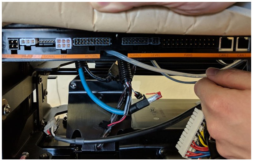
Remove the small pressure sensor tube (a) from the front of the heat exchanger by hand. Route the tube down through the grommet in the frame shelf. The tube remains attached to the controller.
-
Use a T20 Torx to remove the two screws attaching the controller to the frame shelf (b). Save the screws for reuse.
Replace the Cooling Controller
-
Align the new cooling controller against the bottom of the frame shelf. Use a T20 Torx to replace the two screws attaching the controller to the frame. Fasten hand-tight.
-
Route the small pressure sensor tube up through the grommet in the frame and reattach it to the heat exchanger by hand.
Ensure the pressure sensor tube is completely seated and centered on the mount point so that air flow is not constricted. Poor installation can result in a false error alert. -
Reattach all cables to the front of the controller.
-
Gently route the slack of all cooling controller cables back up through the grommet in the frame shelf, to keep them out of the way of the Power Modules.
REVERSE THE ABOVE STEPS TO REPLACE THE REAR EMI
Electromagnetic Interference SHIELD (IF APPLICABLE) AND REAR PANELS.
Power On the Station
Once all cover panels are installed, power on the station. The on-screen Installation Wizard steps you through any required tasks to set up the station and verify that it can operate properly.
An Installation Wizard test checks that all cover panels are correctly installed and fully seated. Check the lower right corner of the screen for any error messages. If panel errors appear, match the panel letters to this illustration.
(a) Front bottom panel
(b) Middle vent panel
(c) Front top panel
(d) LED display
(e) Area light bar
(f) Rear bottom panel
(g) Rear middle panel
(h) Rear top panel
(i) Left extrusion
(j) Right extrusion
If any panel needs re-installation, review the procedures above to double-check that all panels are fully seated and that the edges of all signs are captured fully by the panels around them.