Replace the Wago Label
The ChargePoint Wago label is applied to the upper AC Wago terminals, to discourage servicing or tampering of factory-assembled conductors that should not be adjusted in the field. Newer Express 250 stations have this sticker already applied. Previous stations may need it retrofitted during installation or service.
For assistance, go to chargepoint.com/support and find your region’s technical support number.
Complete the following steps to replace the Wago label in a Express 250 charging station.
Required Tools and Materials
|
|
Head lamp |
|
T25 Torx security screwdriver |
|
|
Stepladder |
|
Permanent marker |
|
|
Isopropyl wipes and towel roll |
|
#2 Phillips screwdriver |
|
|
Lint-free absorbent cloth |
|
8 mm (5/16 mm) nut Torque screwdriver |
|
|
ChargePoint replacement part #CPE250-WAGO TAMPER LABEL-F |
|
T20 Torx screwdriver |
Kit Contents
Sheet of Wago labels
Before you Begin
Complete the following procedures:
Install the Wago Label
-
Remove the AC wiring cover.

-
Perform a pull-push test on all shunt trip wires and conductors above the AC terminals. Ensure all orange buttons are in the up (flush) position as shown.

-
Wipe down the outer sides of the AC terminal block with isopropyl wipes in line with the upper Wago tool ports. Dry the terminal block with a paper towel or clean cloth.

-
Remove the label’s back liner to expose the adhesive.
-
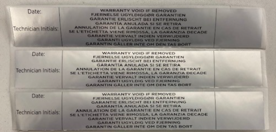
Affix the Wago label onto the station ONLY in the location shown. Use a permanent felt tip pen to mark the label with the installer or service technician’s initials and the date work was performed.

REVERSE THE ABOVE STEPS TO REPLACE THE EMI![]() Electromagnetic Interference SHIELD (IF APPLICABLE), REAR PANELS, FRONT PANELS, LED DISPLAY, AND AREA LIGHT BAR.
Electromagnetic Interference SHIELD (IF APPLICABLE), REAR PANELS, FRONT PANELS, LED DISPLAY, AND AREA LIGHT BAR.
