Replace a Power Module
To replace a power module, complete the steps in this chapter.
Required Tools and Materials
|
|
Head lamp |
|
T25 Torx security screwdriver |
|
|
Stepladder |
|
#2 Phillips screwdriver |
|
|
ChargePoint replacement part #System-PM |
|
8 mm (5/16 mm) nut Torque screwdriver |
Before you Begin
Complete the following procedures:
Remove the Power Module
-
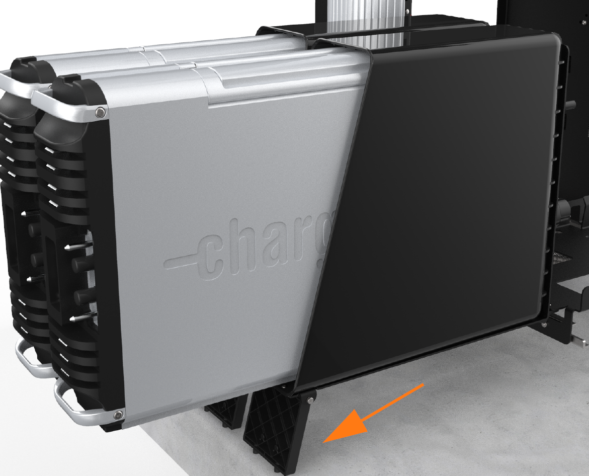
Tilt both Power Module holders down to the ground and rest them on their kickstands (highlighted).
-
To remove a Power Module, slide it partially out of its holder until the handles can be lifted to remove it completely.
The kickstands must rest on a surface that is level with the bottom of the station.
Install the Power Module
-
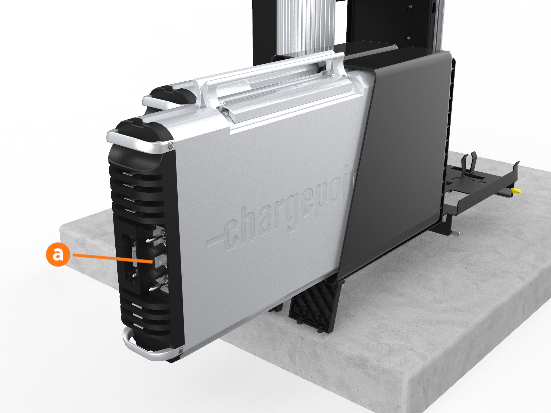
Install the rear Power Module first. Using two people, lift the Power Module by its top handles and gently slide it into its holder with its connections facing outward (a).
-
Once the Power Module is positioned partially inside its holder, fold the handles down to slide it in completely.
-
Repeat the step for the second Power Module if applicable.
-
Lift each Power Module to the upright position one at a time.
-
If ground straps are present:
-
Use a T25 Torx and four M5 screws to attach a ground stud bracket to each side of each Power Module (two brackets and eight screws per Power Module).
-
Use an 8 mm (5/16 in) nut driver, two M5 nuts, and two M5 washers to reattach each ground strap to the ground studs on the sides of both Power Modules.


-
-
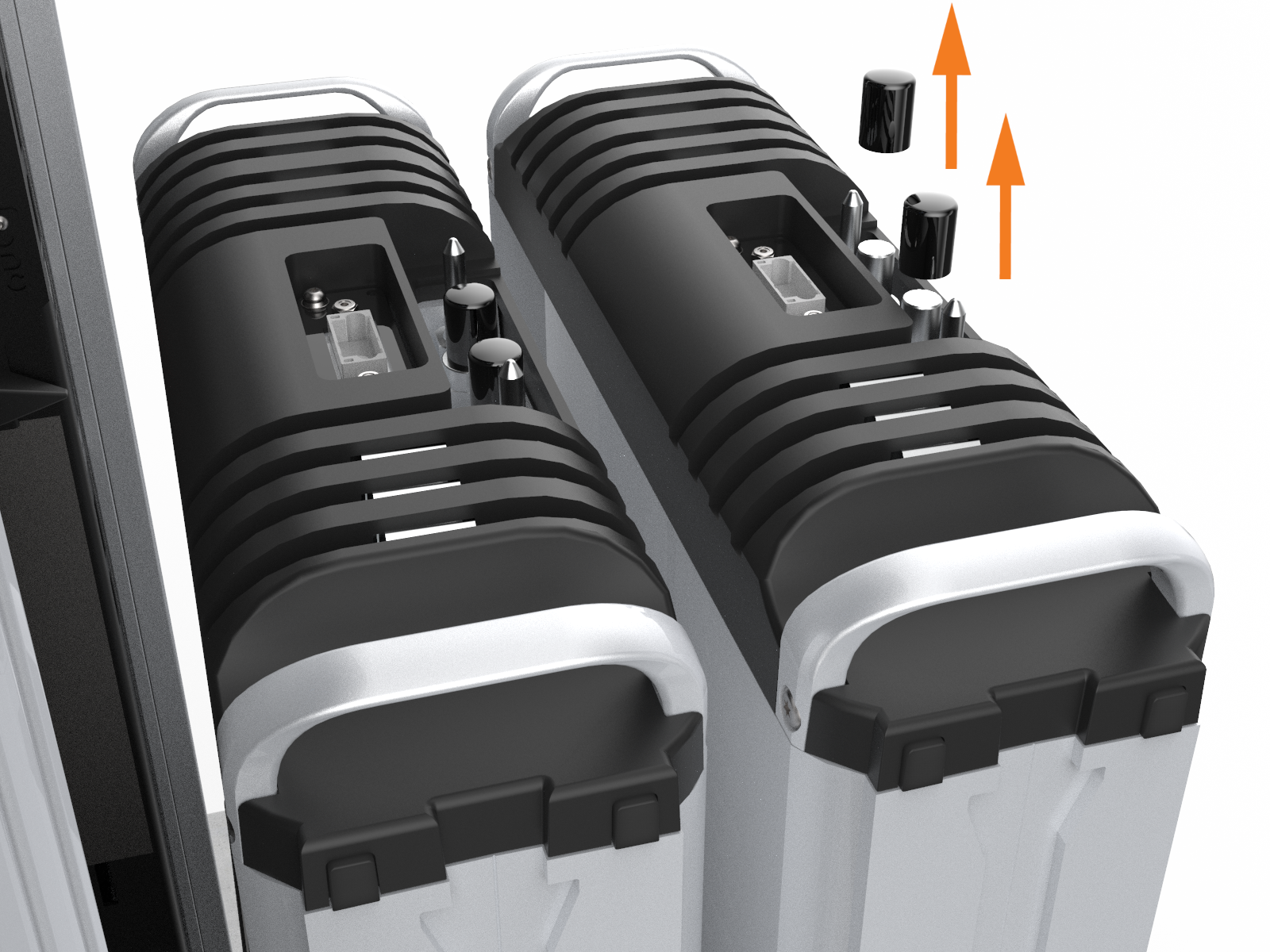
If not already done, remove the safety caps from the coolant ports.
-
At the bottom right of the Express 250, press and hold the yellow release latch while pushing the Power Module tray into the station until it locks into place.
-
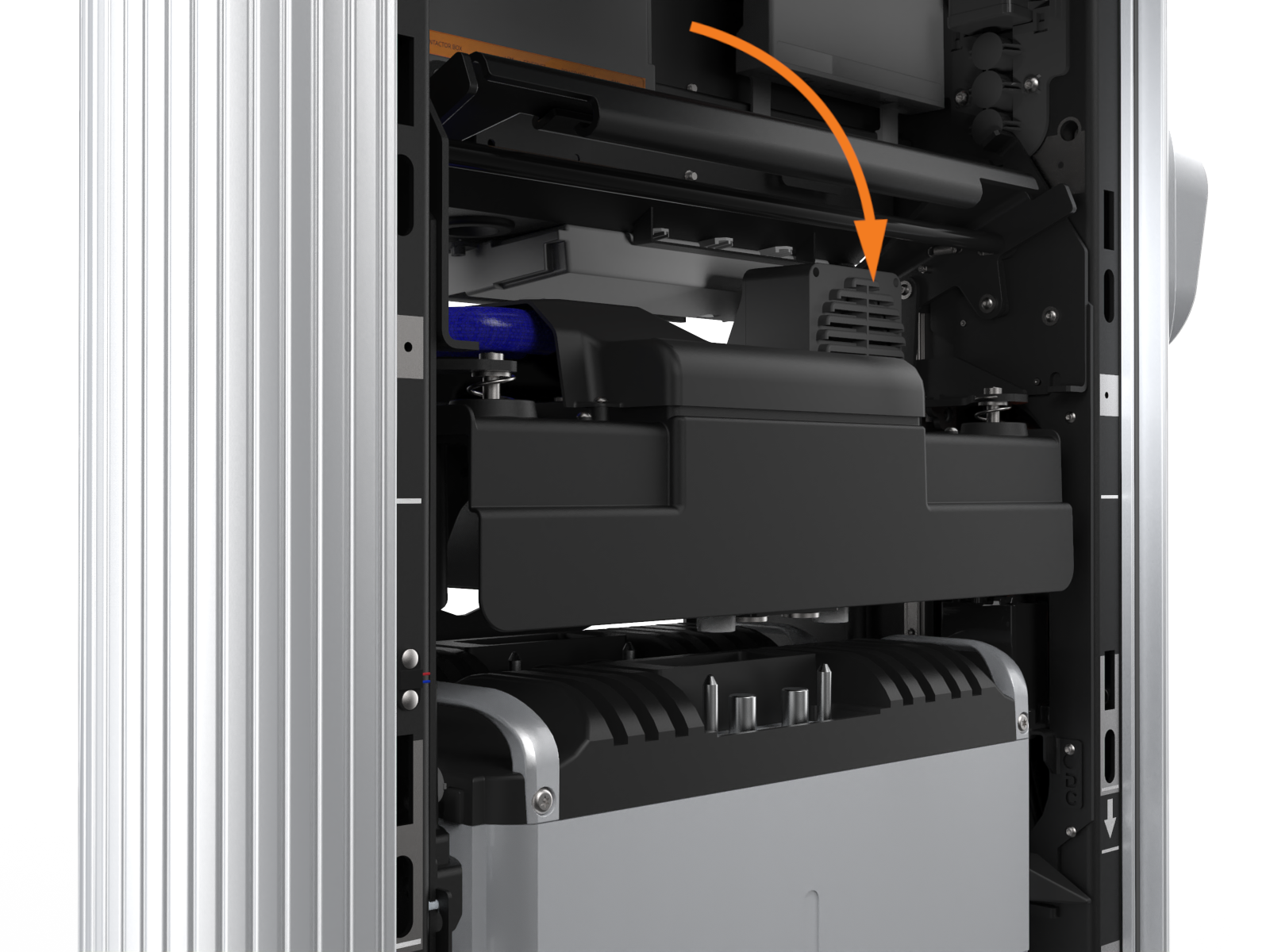
Using two hands, squeeze the Power Module mechanism’s release bar and lower it halfway to check alignment with the ports and guide posts.
-
Lower the Power Module mechanism until you hear a click as the mechanism locks into place. Ensure the mechanism is fully engaged with all Power Module connectors. The Power Module mechanism should fully cover the ridges on the Power Module’s top edge.

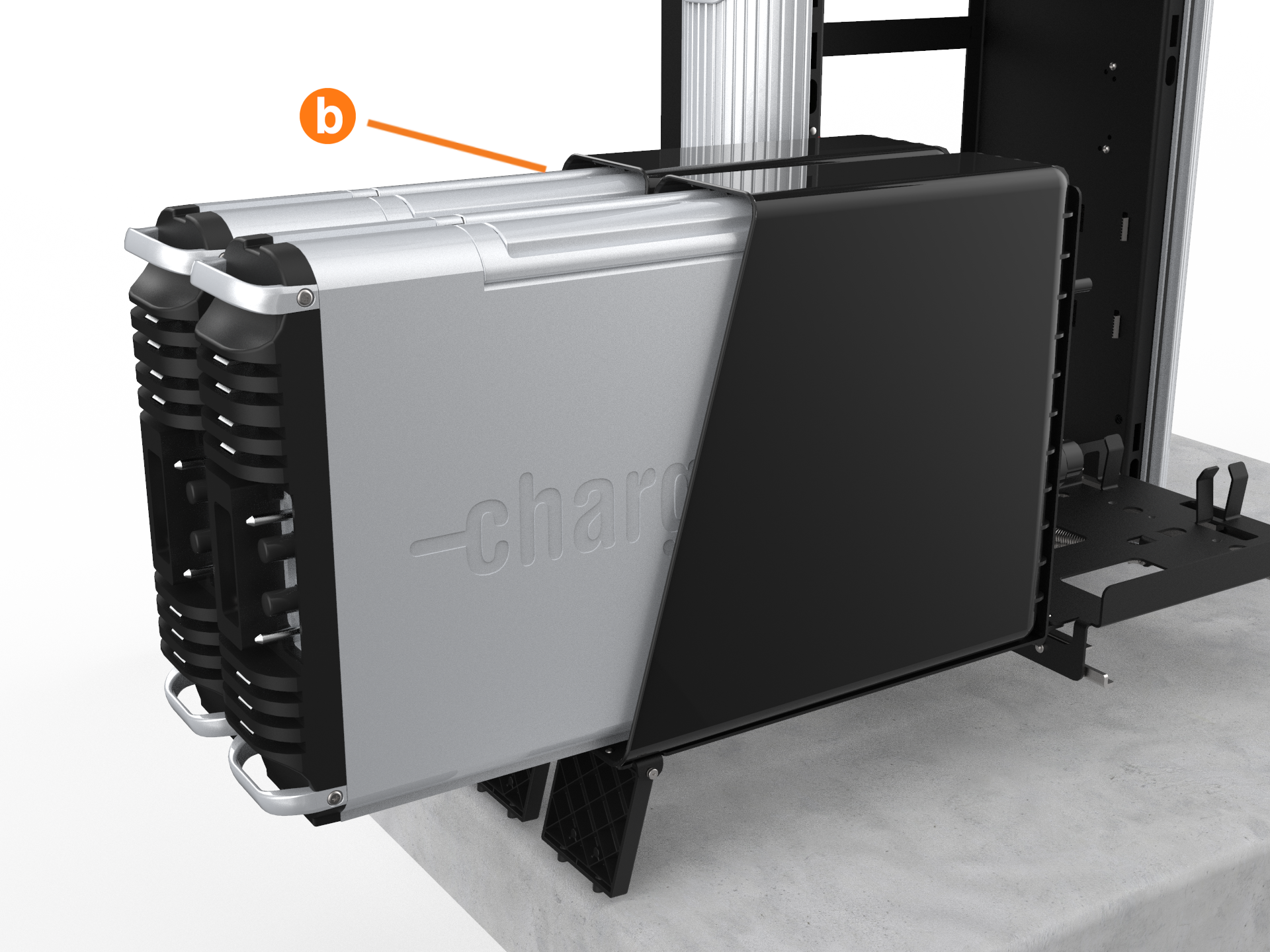
If only one Power Module is being installed, it must be installed in the rear holder (b).

If the mechanism does not engage, raise it again and push the Power Modules to the back of the station to realign, then try again. Do not apply excessive force.
REVERSE THE ABOVE STEPS TO REPLACE THE EMI![]() Electromagnetic Interference SHIELD (IF APPLICABLE), REAR PANELS, FRONT PANELS, LED DISPLAY, AND AREA LIGHT BAR.
Electromagnetic Interference SHIELD (IF APPLICABLE), REAR PANELS, FRONT PANELS, LED DISPLAY, AND AREA LIGHT BAR.
