Replace Charging Cable with a NACS Cable
To replace the charging cable with a NACS![]() North American Charging Standard cable, complete the steps in this chapter.
North American Charging Standard cable, complete the steps in this chapter.
Required Tools and Materials
|
|
Torx screwdriver set
|
|
T25 Torx Security screwdriver |
|
|
10 mm (3/8 in) hex nut driver |
|
Dielectric grease |
|
|
10 mm (3/8 in) socket |
|
Torque paint pen |
|
|
Head lamp |
|
Stepladder |
|
|
Torque wrenches capable of measuring torques from 1.69 Nm (15 in-lb) to 6.8 Nm (60 in-lb) |
Check the Cable Replacement Kit Contents
.")
-
Inspect the new part. Is the part free from shipping damage (damaged insulation, bent or broken pins, etc.)? If the part has any defects, go to chargepoint.com/support and contact technical support using the appropriate region-specific number before beginning work.
-
Place the outer cable clamp surface on a padded surface to protect it from scratches until installed.
Installation Sequence
Inspect the serial number (a) located below the swing arms and above the rear panels on the back of the station.

Follow the installation sequence listed below based on the serial number.
|
Serial Numbers |
Serial Numbers |
|---|---|
Be aware of these important considerations:
-
This guide describes how to replace a CHAdeMO cable with a NACS
 North American Charging Standard cable. For details on replacing a CCS Combined Charging System cable, go to Replace Charging Cable.
-
If the station has a serial number 2133xxxx or higher, you might need to remove the contactor box and move the connectors.
Access the Charging Cables
-
Cables are color-coded. Color codes are different for each installed charge connector type.
CHAdeMO has white and black color codes. NACS North American Charging Standard, CCS1, and CCS2 have red and black color codes.
It is easiest to unfasten all cables for better access, even if only one cable is being replaced. -
Look closely at the upper slot, position 3, on the contactor box (a).
If you do not see a relay through position 3, the station has a 2-relay contactor box and you must remove the contactor box and move the connectors. Complete the steps in Update the Contactor Assembly - Advanced before continuing.
-
If you can see a relay through slot number three, the station has a 3-relay contactor box and you do not need to remove the contactor box. Continue with the steps in this section.
-
Use a 10 mm (3/8 in) nut driver to remove the four CHAdeMO contactor nuts. Save the nuts for later reinstallation.
Remove the CHAdeMO contactor cable lugs (b) from the lug landings (c).
Avoid touching the lug contact area. Handle the cable lugs by their edges. -
Press the retention tab (d) on the back of the CHAdeMO communication cable and remove it from the contactor assembly.
-
Gently remove the CHAdeMO communication cable from the P-clips mounted between the auxiliary power supply and the contactor assembly. The P-clips open at the top.
-
Pull both CHAdeMO cables (communication and conductor) so they hang down at the right side of the charging station in a bundle.
-
Remove the DC ferrite from the cable bundle.
Save the DC ferrite. It must be reinstalled later. If you have a 2-relay contactor box (determined in step 2 above), complete the procedure in Update the Contactor Assembly. After updating the contactor assembly, go to Remove and Replace the Cable in the Swing Arm.
If you have a 3-relay contactor box (determined in step 3 above), continue with steps 9 and 10. -
Use a T20 Torx screwdriver to remove the two M4 screws on each of the lower set of lug landings.
-
Move the lug landings to position 3.
-
Align the each lug landing (f) with the correct guide pin (g) on the contactor box. The positive lug landing has a notched corner (h).
-
To seat lug landing on the contactor box, press the base (i) of the lug landing down.
-
Use a T20 Torx screwdriver to secure the lug landings on the contactor box.
Torque the M4 screws to 1.69 Nm (15 in-lb).


-

| CHAdeMo | CCS |
NACS |
|
|---|---|---|---|
| Positive | white | red | red |
| Negative | black | black | black |


Replace the Top Cable
-
Identify the small data wire attached to the top cable. Unthread it from the tension tab.
-
If the gasket is installed over the top of the cable clamp as shown, cut the gasket away on the top so that it sits in the channel on either side.
-
If you can see the screws (a) holding the cable clamp to the station, skip to step 6.
If you cannot see the screws, complete steps 4 and 5.
-
Use a T25 Torx screwdriver to remove the ten M5 screws securing the cover.
-
Gently lift the cover (b).
-
Use a T25 Torx screwdriver to remove the ten M5 screws holding the cable clamp to the station.
-
Gently move the top cable’s wires to identify them in the overall bundle below. Pulling from inside the top arm, thread the three top cable wires (conductors and communications) up through the body of the station and out through the circular opening at the top of the station.
-
Remove the entire cable from the station.
-
Remove the protective wrapping from the new cable clamp and lift the cable clamp up to the top arm. Insert the cable clamp into the arm so that the screw mounting tabs hold it in place to take the weight of the cable.
-
Use a T25 Torx screwdriver and ten M5 screws to secure the cable clamp assembly to the top arm. Torque to 4.5 Nm (40 in-lbs).
-
Route the three wires (positive, negative, and communications) through the top arm opening. Reach through the top circular opening in the top arm to assist threading the wires through. Once all three connectors are through the circular gasket at the bottom of the bearing stack, continue routing the wires through from below the arms.
-
Position the cable clamp in the arm. For the top arm, align the cable clamp so that the second semicircle in the housing (b) matches the gasket line in the arm.
-
After replacing the top cable, skip to Reinstall the Cables .


 and thread them up through the body of the station and out through the circular opening at the top.")


Replace the Bottom Cable
-
Swing the bottom arm out for access. Use the provided foam block to hold the arm in place.
-
Use a T25 Torx screwdriver to loosen the four M5 captive screws that hold the bottom lid to the station from below.
-
Swing the bottom lid to the outside of the station, to expose the inside of the bottom arm.
-
If the gasket is installed over the top of the cable clamp as shown, cut the gasket away only on the top so that it sits in the channel on either side.
-
Identify the small data wire attached to the top cable. Unthread it from the tensioner tab.
-
Use a T25 Torx screwdriver to remove the ten M5 screws holding the cable clamp to the station.
-
Reposition the bottom arm to extend only 45 degrees out from the station. This maximizes the size of the wiring opening. Re-block with the foam block.
-
Gently move the bottom cable’s wires to identify them in the overall bundle below. Pulling from inside the bottom arm, thread the three bottom cable wires (conductors and communications) up through the body of the station and out. Remove the entire cable from the station.
-
Remove the protective wrapping from the new cable clamp and lift the cable clamp up to the bottom arm. Insert the cable clamp into the slot in the arm so that the screw mounting tabs hold it in place to take the weight of the cable.
-
Use a T25 Torx screwdriver and ten M5 screws to secure the cable clamp assembly to the bottom arm. Torque to 4.5 Nm (40 in-lb).
-
Route the three wires (positive, negative, and communications) through the bottom arm opening where it meets the station. Reach through the top circular opening in the top arm to assist threading the wires through. Once all three connectors are through the circular gasket at the bottom of the bearing stack, continue routing the wires through from below the arms.
-
Position the cable clamp in the arm. For the bottom arm, align the cable clamp so that the first semicircle in the housing (a) matches the gasket line in the arm.
-
Proceed to the next section to reassemble the station.


 through the bottom arm opening.")

Reassemble the Station
Refer to the images in the procedures above while replacing the station components:
-
Reinstall the ten screws that hold the cable clamp to its arm. Torque to 4.5 Nm (40 in-lb).
-
Gently route the data wire through the tensioner, being careful not to overstress or cut the wire.
-
If you removed the cover to access the cable clamp screws, replace the ten screws that hold the cover in place. Torque to 5.3 Nm (47 In-lb).
-
Check gasket placement to ensure it sits inside the channel all around the arm.
-
Replace the lid on top of its arm. From below, use a T25 Torx screwdriver to fasten the four captive screws. Torque to 2.6 Nm (20 in-lb).
For the bottom lid, lift up slightly on the lid to help it clear the arm and gasket. -
Remove the foam block used to hold the swing arm open and allow the arm to swing back to home position.
-
Replace the top lid.
-
Route the communication cables through the plastic P-clips above the contactor box.
-
Plug communication cables in on the left side of the contactor assembly, paying attention to which cable belongs in positions 1, 2, and 3.
2-relay contactor boxes (boxes where the connectors were moved) have two active slots. Route the power connectors through slots 1 and 2. Connect the communications cables into slots 2 and 3 respectively.2-relay contactor box

(a) NACS
North American Charging Standard communication cable(b) NACS
North American Charging Standard DC charging cable(c) CCS
Combined Charging System communication cable(d) CCS
Combined Charging System DC charging cable3-relay contactor box

(a) NACS
North American Charging Standard communication cable(b) NACS
North American Charging Standard DC charging cable(c) CCS
Combined Charging System communication cable(d) CCS
Combined Charging System DC charging cable -
Apply a thin layer of dielectric grease to the face of each lug on the contact surface.
Ensure that the DC ferrite is reinstalled before replacing the contactor lugs. -
Replace contactor lugs with two nuts each, according to the previously taken pictures.
-
Match positive and negative signs on the conductor labels to the signs imprinted on the plastic face of the contactor assembly. CHAdeMO is always in position 1 (lowest) when present. Torque to 6.8 Nm (60 in-lb) and mark with a paint pen.
Do not install the contactor lugs with reversed positive/negative polarity. Incorrect polarity could damage the station or the vehicle charging from the station. -
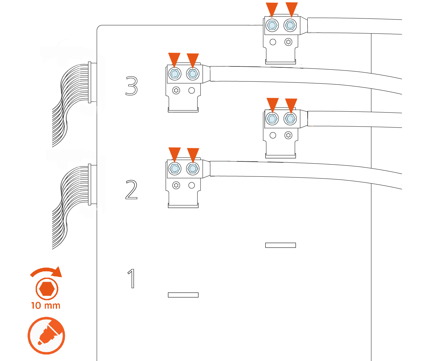
Use a calibrated torque wrench with a 10 mm (3/8 in) socket to retorque the nuts on all lugs of the contactor assembly to 6.8 Nm (60 in-lb), as shown in the images below. Mark the nuts with a paint pen.
There are up to three possible charge connector slots shown as 1, 2, and 3 on the front plastic cover of the contactor assembly.See the following examples of 2-relay and 3-relay connector boxes for reference:
Example: 2-relay contactor box
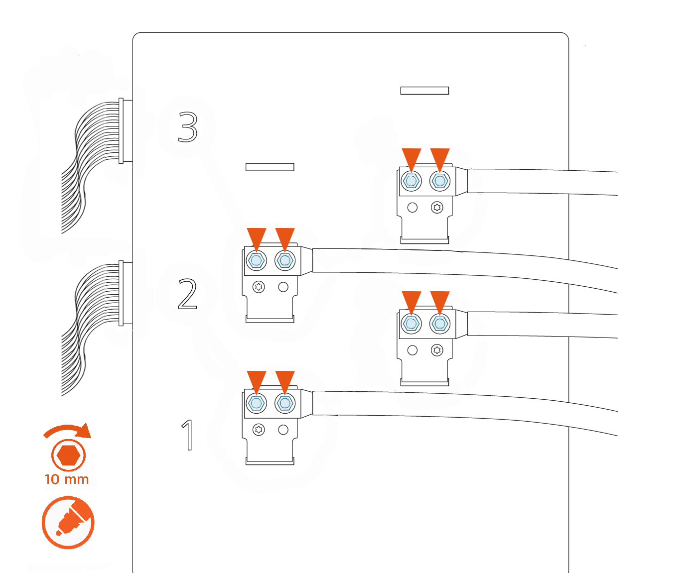
Example: 3-relay contactor box
Remove and Replace Cable in Swing Arm
-
Unholster both cables and put them on a padded surface.
-
Swing the top arm out for access. Use the provided foam block (a) to hold the arm in place.
-
Use a T25 Torx screwdriver to loosen the four M5 captive screws that hold the top lid to the station from below. Set the top lid on a padded surface. The top lid must be removed whether the top or bottom cable is being replaced.
-
Identify the small data wire attached to the top cable. Unthread it from the tension tab.
The data wire is a different color depending on the type of cable. -
If the gasket is installed over the top of the cable clamp as shown, cut the gasket away on the top so that it sits in the channel on either side.
-
If you can see the screws (b) holding the cable clamp to the station, skip to step 9.
If you cannot see the screws, complete steps 7 and 8.
-
Use a T25 Torx screwdriver to remove the ten M5 screws securing the cover.
-
Gently lift the cover (c) so you can access the screws in step 9.
-
Use a T25 Torx screwdriver to remove the ten M5 screws holding the cable clamp to the station.
-
Gently move the top cable’s wires to identify them in the overall bundle below. Pulling from inside the top arm, thread the three top cable wires (conductors and communications) up through the body of the station and out through the circular opening at the top of the station.
-
Remove the entire cable from the station.
Follow recommended product disposal guidelines when discarding the cable.
-
Remove the protective wrapping from the new cable clamp and lift the cable clamp up to the top arm. Insert the cable clamp into the arm so that the screw mounting tabs hold it in place to take the weight of the cable.
-
Position the cable clamp in the arm. For the top arm, align the cable clamp so that the second semicircle in the housing (b) matches the gasket line in the arm.
-
Use a T25 Torx screwdriver and ten M5 screws to secure the cable clamp assembly to the top arm. Torque to 4.5 Nm (40 in-lbs).
-
Route the three wires (positive, negative, and communications) through the top arm opening. Reach through the top circular opening in the top arm to assist threading the wires through. Once all three connectors are through the circular gasket at the bottom of the bearing stack, continue routing the wires through from below the arms inside the station.
-
Ensure that the DC ferrite is reinstalled before replacing the contactor lugs.
-
Gently route the data wire through the tensioner, being careful not to overstress or cut the wire.
-
If you removed the cover to access the cable clamp screws, replace the ten screws that hold the cover in place. Torque to 4.5 Nm (40 in-lb).
-
Check gasket placement to ensure it sits inside the channel all around the arm.
-
Replace the lid on top of its arm. From below, use a T25 Torx screwdriver to fasten the four captive screws. Torque to 2.6 Nm (20 in-lb).
For the bottom lid, lift up slightly on the lid to help it clear the arm and gasket.


Reinstall the Cables
Refer to the images in the procedures above while replacing the station components:
Route the communication cables through the plastic P-clips above the contactor box.
Plug communication cables on the left side of the contactor assembly, paying attention to which cable belongs in positions 1, 2, and 3.
3-relay Contactor Box
(a) NACS
North American Charging Standard communication cable(b) NACS
North American Charging Standard DC charging cable(c) CCS
Combined Charging System communication cable(d) CCS
Combined Charging System DC charging cableEnsure the 2-relay contactor box has been updated as described in Update the Contactor Assembly - Advanced before completing this step.
2-relay Contactor Box
2-relay contactor boxes (boxes where the connectors were moved) have two active slots. Route the power connectors through slots 1 and 2.(a) NACS
North American Charging Standard communication cable(b) NACS
North American Charging Standard DC charging cable(c) CCS
Combined Charging System communication cable(d) CCS
Combined Charging System DC charging cableApply a thin layer of dielectric grease to the face of each lug on the contact surface.
Match positive and negative signs on the conductor labels to the signs imprinted on the plastic face of the contactor assembly. Torque to 6.8 Nm (60 in-lb) and mark with a paint pen.
Do not install the contactor lugs with reversed positive/negative polarity. Incorrect polarity could damage the station or the vehicle charging from the station.Replace contactor lugs with two nuts each, according to the images.
Tuck the excess contactor cable down the side of the enclosure to avoid interfering with the cover panel in a later step.
Visit Replace a Holster for instructions on replacing the holster.
Use a calibrated torque wrench with a 10 mm (3/8 in) socket to retorque the nuts on all lugs of the contactor assembly to 6.8 Nm (60 in-lb), as shown in the images below. Mark the nuts with a paint pen.
There are up to three possible charge connector slots shown as 1, 2, and 3 on the front plastic cover of the contactor assembly.See the following examples of 2-relay and 3-relay connector boxes for reference:
Example: 2-relay contactor box
Example: 3-relay contactor box
REVERSE THE ABOVE STEPS TO REPLACE THE TOP FRONT PANEL, LED DISPLAY, AND AREA LIGHT BAR.
Update the Contactor Assembly - Advanced
Remove the Contactor Box
-
Use a 10 mm (3/8 in) nut driver to remove the four CCS
Combined Charging System contactor nuts. Save the nuts for later reinstallation. -
Remove the CCS
Combined Charging System contactor cable lugs (a) from the lug landings (b).Avoid touching the lug contact area. Handle the cable lugs by their edges. -
Press the retention tab (c) on the back of the communication cable and remove it from the contactor assembly.
-
Remove the horizontal 50-pin ribbon cable (d). Push the tabs outward. Rock it gently from left to right as you pull out the cable.
-
Remove the remaining three CCS
Combined Charging System cables connected to the left side of the contactor assembly: 24 V DC power (e), and CAN connectors (f).Each cable is keyed to its corresponding connector except the CAN cables, which are interchangeable. -
Open the securing latches (g) on the left and right sides of the contactor box assembly by pushing down on the lock tab and lifting the lever.
-
Disengage the contactor assembly from the large bus bar connections at the bottom (h) by holding it with two hands near the bottom and rocking the assembly slightly as you pull outward.
-
Once the bus bar connections release, pull the assembly forward along the support arms (i), then lift it away from the station.
Avoid touching the tab contact area. Handle the cable tabs by their edges.


Move the Connectors
-
Use a T25 Torx screwdriver to remove the three screws (a) securing the cover.
-
Remove the cover.
-
Unplug the 8-pin contactor connector from position 2 (b) and plug it into position 3 (c).
-
Unplug the 8-pin contactor connector from position 1 (d) and plug it into position 2 (b).
-
Replace the cover. Use a T25 Torx screwdriver and three screws to secure the cover.
-
Place the included label on the contactor box indicating the updated slot numbers.


Replace the Contactor Assembly
-
Ensure latch clasps are open and not blocking the contactor assembly before installation.
-
Rest the alignment pegs of the contactor assembly on the support arm hooks.
-
Slide the contactor assembly back along the support arms. Push the assembly to engage the bus bars until fully seated.
Ensure the connectors are aligned before pressing in. Do not apply excessive force. Doing so can damage the connectors. Once seated, gently pull the contactor assembly outward as a push-pull test to confirm it is securely seated.Ensure all cables are accessible without being pinched or caught under the contactor assembly. -
Fasten the latches on the right and left sides of the contactor assembly.
-
Reconnect each cable on the left side of the contactor assembly.

(a) DCC
Dispenser Charge Controller communication ribbonEnsure the key aligns with the notch in the socket.(b) 24 V DC power
(c) CAN connectors (interchangeable)
Secure connector body to the mating connector on the contactor assembly and ensure the tabs are in the open position. During connection the insertion tabs automatically click into place. -
Go to Replace the Swing Arm Assembly. Continue with the steps to replace the charging cable.
