Replace the Contactor Assembly
To replace the contactor assembly, complete the steps in this chapter.
Required Tools and Materials
|
|
Head lamp |
|
T25 Torx security screwdriver |
|
|
Stepladder |
|
90% Isopropyl wipes and towel roll |
|
|
T20 Torx screwdriver |
|
10 mm (3/8 in) socket |
|
|
Torque wrench for 2.8 Nm (25 in-lb) and 6.8 Nm (60 in-lb) |
|
Torque paint pen |
|
|
ChargePoint replacement part #CPE250-CONTACTBOX-F |
|
Before you Begin
Complete the following procedures:
Remove the Contactor Assembly
Before work, take a picture of which cable tab plugs into which slot on the contactor assembly. Cables are color-coded (black is positive, red is negative). Color codes are different for each installed charge connector type. It is critical that the cables are reattached to their original locations.
-
Using a T20 Torx driver, remove the screws (a) that attach the cable tabs to the front of the contactor assembly.

-
Remove the cable tabs by moving them slightly back and forth while pulling straight out to release.
Avoid touching the tab contact area. Handle the cable tabs by their edges.There are up to three possible charge connector slots shown as 1, 2, and 3 on the front plastic cover (b). Note the position of each communication connector before removal. Each cable must be reattached to its original connector slot on the contactor assembly. Failure to do so may damage the station or vehicle. If the original connector location is unknown, the cable can be attached to the contactor assembly based on the connector type indicated by the label: CCS1/CCS2: #2 or #3 CHAdeMO: #1.
-
Remove all cables connected to the left side of the contactor assembly:
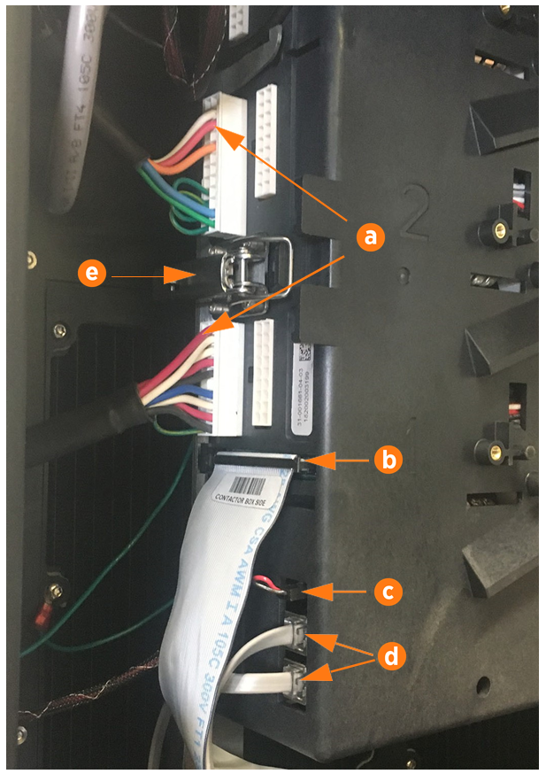
(a) Charge cable communications
(b) DCC
 Dispenser Charge Controller communication ribbon cable
(c) 24 V DC power
(d) CAN connectors
To remove the horizontal ribbon cable, push the tabs outward. Rock it gently from left to right as you pull out the cable.Each cable is keyed to its corresponding connector except the CAN cables, which are interchangeable.
-
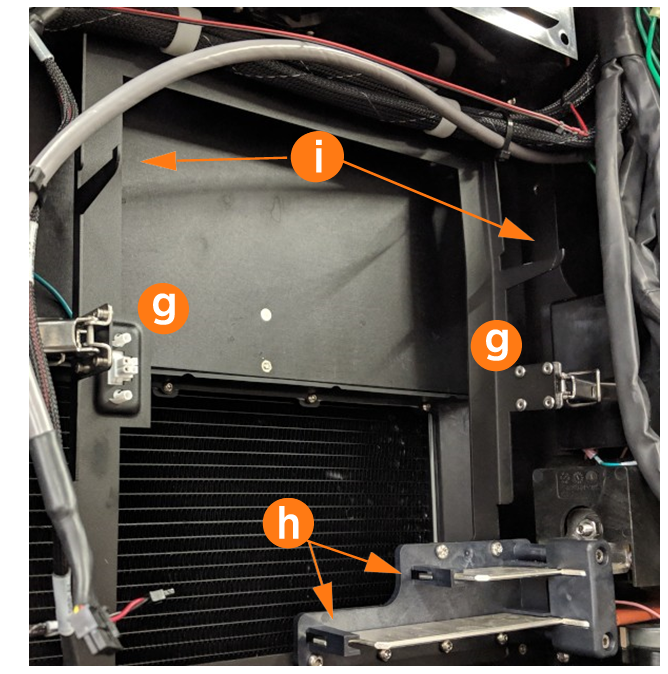
Open the securing latches (g) on the left and right sides of the contactor box assembly by pushing down on the lock tab and lifting the lever (e).
-
Disengage the contactor assembly from the large bus bar connections at the bottom (h) by holding it with two hands near the bottom and rocking the assembly slightly as you pull outward.
-
Once the bus bar connections release, pull the assembly forward along the support arms (i), then lift free from the station.
 Avoid touching the tab contact area. Handle the cable tabs by their edges.
There are up to three possible charge connector slots (shown as 1, 2, and 3 on the front plastic cover). Note the position of each communication connector before removal.
Replace the Contactor Assembly
-
Ensure latch clasps are open and not blocking the contactor assembly before installation.
-
Rest the alignment pegs of the contactor assembly on the support arm hooks.
-
Slide the contactor assembly back along the support arms. Push the assembly to engage the bus bars until fully seated.
Ensure the connectors are aligned before pressing in. Do not apply excessive force. Doing so can damage the connectors. Once seated, gently pull the contactor assembly outward as a push-pull test to confirm it is securely seated.
Ensure all cables are accessible without being pinched or caught under the contactor assembly. -
Fasten the latches on the right and left sides of the contactor assembly.
-
Reconnect each cable on the left side of the contactor assembly.
-
Wipe down the contact surface of each cable tab with isopropyl alcohol wipes.
-
After double-checking the photo of the cable order, push each cable tab into its corresponding slot. Ensure the plastic guide post is fully seated to be level with the surface of the cable tab.
-
Use a T20 Torx driver to re-fasten the screw (a) on each cable tab. Torque to 2.8 Nm (25 in-lb).
-
Tuck the excess contactor cable down the side of the enclosure to avoid interfering with the cover panel in a later step.
(a) Charge cable communications
(b) DCC
Dispenser Charge Controller communication ribbonEnsure the key aligns with the notch in the socket.(c) 24 V DC power
(d) CAN connectors (interchangeable)
Secure connector body to the mating connector on the contactor assembly and ensure the tabs are in the open position. During connection the insertion tabs will automatically close onto the connector housing.
-
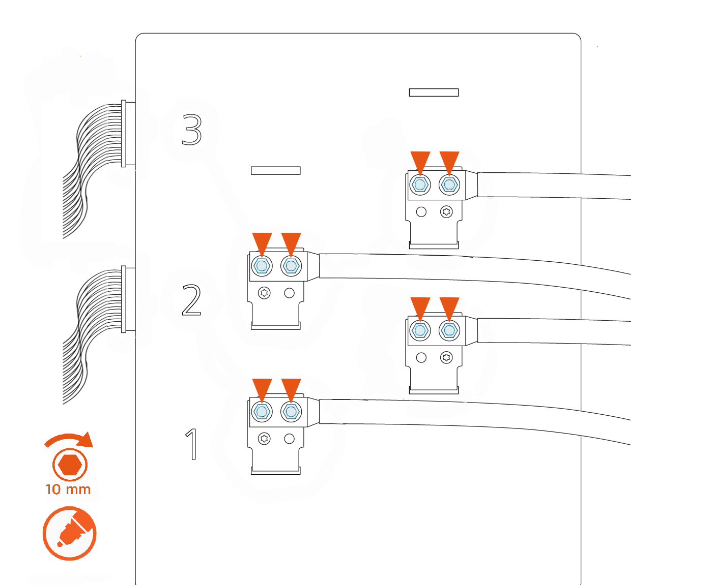
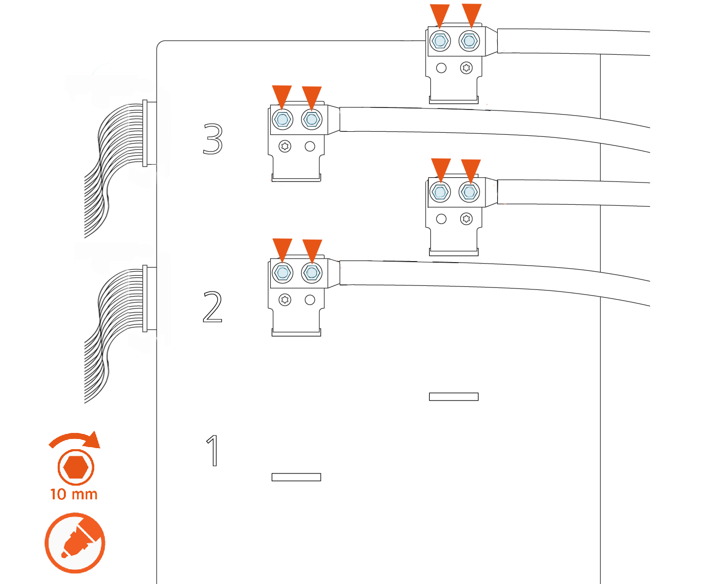
Use a calibrated torque wrench with a 10 mm (3/8 in) socket to retorque the nuts on all lugs of the contactor assembly to 6.8 Nm (60 in-lb), as shown in the images below. Mark the nuts with a paint pen.
There are up to three possible charge connector slots shown as 1, 2, and 3 on the front plastic cover of the contactor assembly.See the following examples of 2-relay and 3-relay connector boxes for reference:
Example: 2-relay contactor box
Example: 3-relay contactor box
REVERSE THE ABOVE STEPS TO REPLACE THE TOP FRONT PANEL, LED DISPLAY, AND AREA LIGHT BAR.
