Replace the Heat Exchanger Assembly
To replace the heat exchanger assembly, complete the steps in this chapter.
Required Tools and Materials
|
|
Head lamp |
|
T25 and T27 Torx security screwdriver |
|
|
Stepladder |
|
Lint-free absorbent cloth |
|
|
T10 and T20 Torx screwdriver |
|
#2 Phillips screwdriver |
|
|
ChargePoint replacement part #CPE250-HEATEX-F |
|
Coolant (included with replacement part) |
Before you Begin
Complete the following procedures:
Remove the Ground Screw

-
From the front of the charging station, look to the left of the contactor assembly. Identify the heat exchanger ground wire.
-
Using a T10 Torx, remove the heat exchanger ground screw from the radiator and save it for later use.
Remove the Fan Tray Assemblies
-
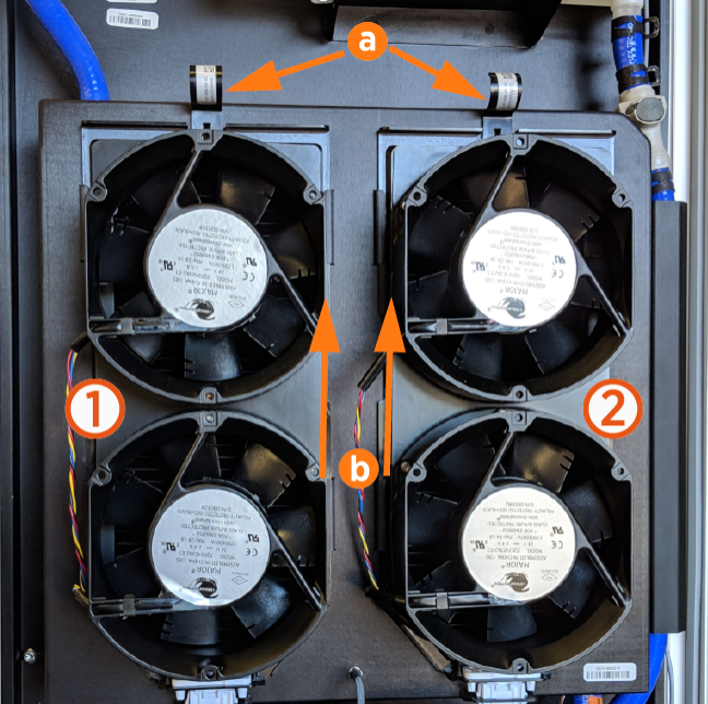
The system has two fan trays (left and right). On each tray, pull the tab (a) at the top of the fan tray assembly forward to disengage it.
-
Using two hands, slide the tray upward until the mounting tabs (b) on the fan tray assembly are positioned above their corresponding slots.
-
Pull the fan tray assembly toward you to remove it.
-
Repeat for the other fan tray.
-
When replacing the fan tray:
-
Ensure all four tabs on the fan tray assembly are positioned above their corresponding slots.
-
Press the fan tray assembly against the Express 250, then slide the fan tray downward.
-
Ensure each tab on the fan tray is located under, and not over, its corresponding slot.
-
Ensure the top tabs are engaged into the metal housing behind them.
-
Ensure the fan’s power connector at the bottom seats correctly.
Fan tray zip ties do not need to be replaced.
-
Zip ties on the fan tray must be cut off to remove the fan tray assembly.
Check that the power connector at the base of the fan assembly easily disengages as the fan tray is lifted.

Remove the Cooling Controller
-
Identify the cooling controller, located behind the protective foam edging on the middle frame shelf.

-
Remove each cable attached to the front of the cooling controller by pressing in on its tab and pulling out by hand (listed left to right):
The CAN cables are interchangeable.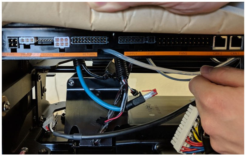
-
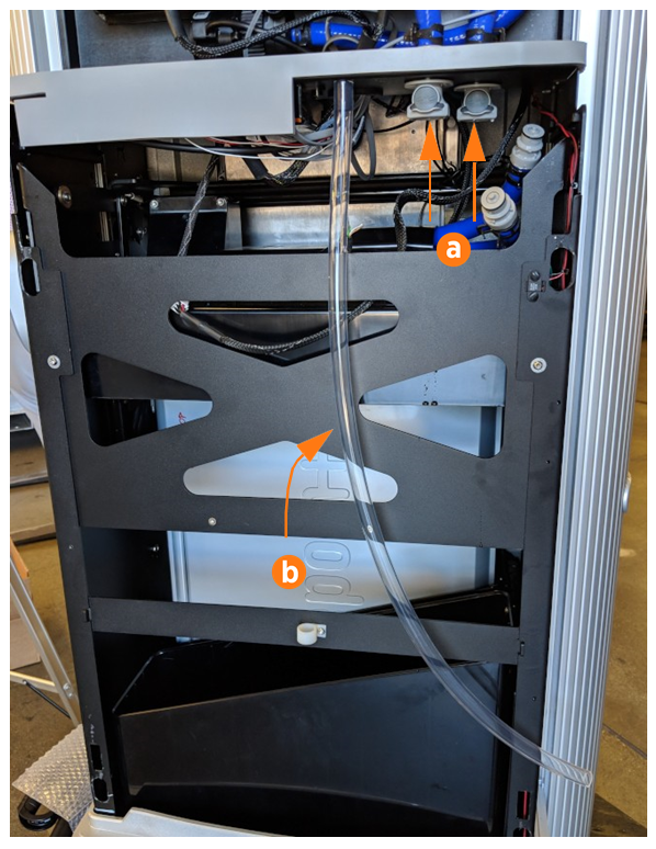
Remove the small pressure sensor tube (a) from the front of the heat exchanger by hand. Route the tube down through the grommet in the frame shelf. The tube remains attached to the controller.
-
Use a T20 Torx to remove the two screws attaching the controller to the frame shelf (b). Save the screws for reuse.

Ensure the pressure sensor tube is completely seated and centered on the mount point so that air flow is not constricted. Poor installation can result in a false error alert.

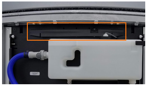
Remove the Heat Exchanger Assembly
Before removing the heat exchanger, hold a clean, lint-free absorbent cloth below the Quick Connect coolant lines to prevent the liquid from spilling onto the Express 250’s other components.
-
For each of the two coolant lines (a), push the button on the Quick Connect at the bottom of the heat exchanger assembly and pull to disconnect the coolant line from the heat exchanger assembly.
-
Pull the overflow hose (b) out of its corresponding retaining clip.
-
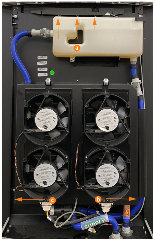
Using a T27 Torx driver, remove the five screws from the heat exchanger assembly. Three screws are located along the top edge behind a gasket (a), one is located at the bottom right (b), and one at the bottom left (c).
-
Pull the overflow hose (b) out of its corresponding retaining clip.
-
Pull the heat exchanger assembly away from the Express 250.
-
Drain all coolant from the heat exchanger assembly to prepare for return shipping.
For easy of assembly, the heat exchanger is self-supported with all five screws removed.
Ensure the gasket is not torn or damaged during removal and replacement of the heat exchanger.
Replace the Heat Exchanger Assembly
-
Hang the new assembly onto the two pins on the frame to support it.
-
Slightly move the assembly left to right a few millimeters until the top screw holes align. Fasten the five T27 screws, beginning with the three screws across the top edge.
-
Fasten the ground wire screw.
-
Fill the heat exchanger assembly’s reservoir to the marked fill line with coolant.
Ensure that wires are not pinched when reinstalling the heat exchanger assembly.
REVERSE THE ABOVE STEPS TO REPLACE THE COOLING CONTROLLER, FAN TRAY, EMI![]() Electromagnetic Interference SHIELD (IF APPLICABLE), REAR PANELS, TOP FRONT PANEL, LED DISPLAY, AND AREA LIGHT BAR.
Electromagnetic Interference SHIELD (IF APPLICABLE), REAR PANELS, TOP FRONT PANEL, LED DISPLAY, AND AREA LIGHT BAR.
