Replace the Auxiliary Power Supply
Complete the following steps to replace the auxiliary power supply in an Express 250 charging station.
Required Tools and Materials
-
ChargePoint replacement part #CPE250-AUXPOWER-F
-
T25 Security Torx driver
-
Headlamp
About Panels
All panels have guide tabs that align with corresponding slots on the product’s frame. When removing a panel, lift the panel upward to release these tabs from their slots.
Power Off the Station
Power off at the breaker panel and lock out/tag out before continuing work.
RISK OF SHOCK. Before performing this procedure, disconnect the power to the station at the service panel. Keep power off for this circuit until all cover panels are correctly reinstalled and the work scope is completed. FAILURE TO FOLLOW THESE INSTRUCTIONS CAN RESULT IN SERIOUS INJURY OR LOSS OF LIFE.
Remove the Area Light Bar
-
Using a T25 Security screwdriver, loosen the two captive screws on the area light bar.
-
Disconnect the power cable that connects the area light bar to the LED display assembly. Remove the area light bar.
When reinstalling, ensure the gasket on each end of the area light bar is properly seated around the plastic tab.
Remove the LED Display
-
Push the LED display upward to release its guide tabs from their corresponding slots on the Express 250’s frame.
-
When the LED display assembly is released, disconnect the five cables from the back.
When reinstalling, connect the five cables to their corresponding connectors on the back of the display. Leave the area light bar cable (e) loose.
(a) Communications cable (USB
Universal Serial Bus-A)(b) Holster light cable
(c) Area light cable x 2 (interchangeable)
(d) Power cable (24 V)
Do not allow the LED display to hang from its cables.
Remove the Top Front Panel
-
Using two hands, pull the top panel upward to release its guide tabs from their corresponding slots on the Express 250’s frame.
-
Place a protective cover, such as a lint-free cloth, over the touchscreen to prevent damage during service.
When reinstalling, push the bottom edge inward to position it inside the groove in the middle vent panel and engage the edge of the sign. Carefully push the panel down until it is firmly seated.
When reinstalling, ensure all five cables at the top of the panel are not captured by the front upper panel, and are easily accessible for reinstalling the LED display.
Remove the Auxiliary Power Supply
-
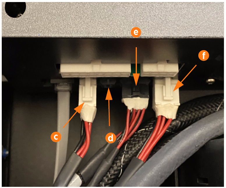
Disconnect the five connectors from the auxiliary power supply:
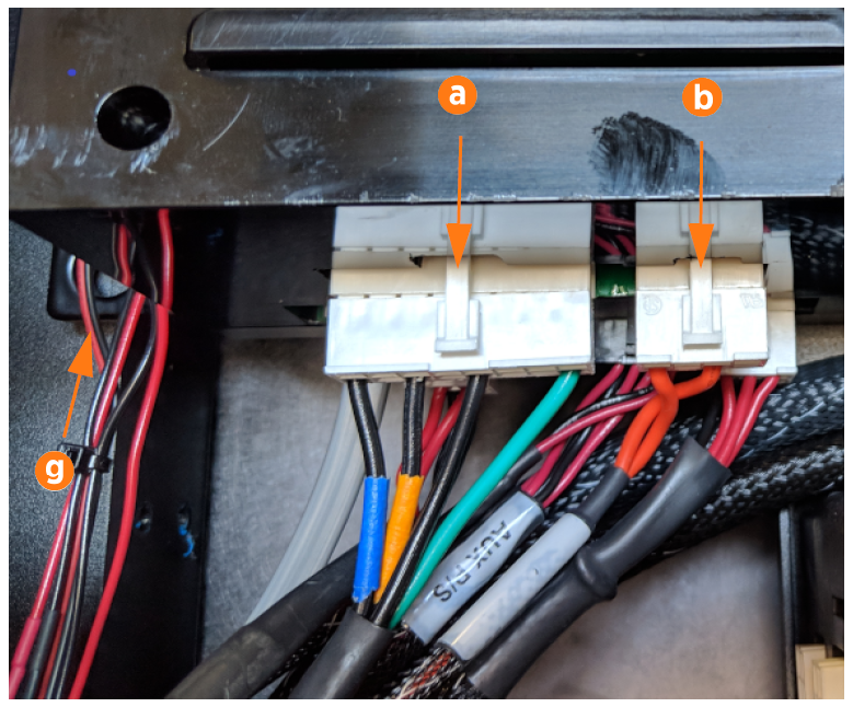
(a) 480 V power in
(b) Shunt trip relay connector
(c) CAN bus in
(d) Cooling I/O
(e) 12 V power out to internal components
(f) LED display 5 V
Use a T25 Torx driver to loosen the four screws at the corners of the auxiliary power supply. Do not fully remove screws: leave the screws in the charging station and move the power supply sideways to release it from the keyhole mounting tabs (g).
When reinstalling, torque the four screws hand-tight. -
Slide the auxiliary power supply toward you to remove it.
REVERSE THE ABOVE STEPS TO REPLACE THE NEW AUXILIARY POWER SUPPLY, TOP FRONT PANEL, LED DISPLAY, AND AREA LIGHT BAR.
Power On the Station
Once all cover panels are installed, power on the station. The on-screen Installation Wizard steps you through any required tasks to set up the station and verify that it can operate properly.
An Installation Wizard test checks that all cover panels are correctly installed and fully seated. Check the lower right corner of the screen for any error messages. If panel errors appear, match the panel letters to this illustration.
(a) Front bottom panel
(b) Middle vent panel
(c) Front top panel
(d) LED display
(e) Area light bar
(f) Rear bottom panel
(g) Rear middle panel
(h) Rear top panel
(i) Left extrusion
(j) Right extrusion
If any panel needs re-installation, review the procedures above to double-check that all panels are fully seated and that the edges of all signs are captured fully by the panels around them.