Replace the I/O Expander
To replace the I/O expander, complete the following steps:
Required Tools and Materials
-
ChargePoint replacement part #CPE250-FRONT-PANELS-F
-
T25 Security Torx driver
-
Headlamp
About Panels
All panels have guide tabs that align with corresponding slots on the product’s frame. When removing a panel, lift the panel upward to release these tabs from their slots.
Power Off the Station
Power off at the breaker panel and lock out/tag out before continuing work.
RISK OF SHOCK. Before performing this procedure, disconnect the power to the station at the service panel. Keep power off for this circuit until all cover panels are correctly reinstalled and the work scope is completed. FAILURE TO FOLLOW THESE INSTRUCTIONS CAN RESULT IN SERIOUS INJURY OR LOSS OF LIFE.
Remove the Area Light Bar
-
Using a T25 Security screwdriver, loosen the two captive screws on the area light bar.
-
Disconnect the power cable that connects the area light bar to the LED display assembly. Remove the area light bar.
When reinstalling, ensure the gasket on each end of the area light bar is properly seated around the plastic tab.
Remove the LED Display
-
Push the LED display upward to release its guide tabs from their corresponding slots on the Express 250’s frame.
-
When the LED display assembly is released, disconnect the five cables from the back.
When reinstalling, connect the five cables to their corresponding connectors on the back of the display. Leave the area light bar cable (e) loose.
(a) Communications cable (USB
Universal Serial Bus-A)(b) Holster light cable
(c) Area light cable x 2 (interchangeable)
(d) Power cable (24 V)
Do not allow the LED display to hang from its cables.
Remove the Top Front Panel
-
Using two hands, pull the top panel upward to release its guide tabs from their corresponding slots on the Express 250’s frame.
-
Place a protective cover, such as a lint-free cloth, over the touchscreen to prevent damage during service.
When reinstalling, push the bottom edge inward to position it inside the groove in the middle vent panel and engage the edge of the sign. Carefully push the panel down until it is firmly seated.
When reinstalling, ensure all five cables at the top of the panel are not captured by the front upper panel, and are easily accessible for reinstalling the LED display.
Remove the I/O Expander Unit
-
Use a T25 Torx driver to remove the M5 screw and washer attaching each touchscreen ground strap to the frame. Keep the screws and washers for reuse.
-
Loosen both retention knobs (a), allowing the touchscreen beam (b) to slide up vertically and the touchscreen’s bottom edge to clear the middle vent panel’s slot (c).
-
With hand pressure, tilt the touchscreen upward at a 45-degree angle.
-
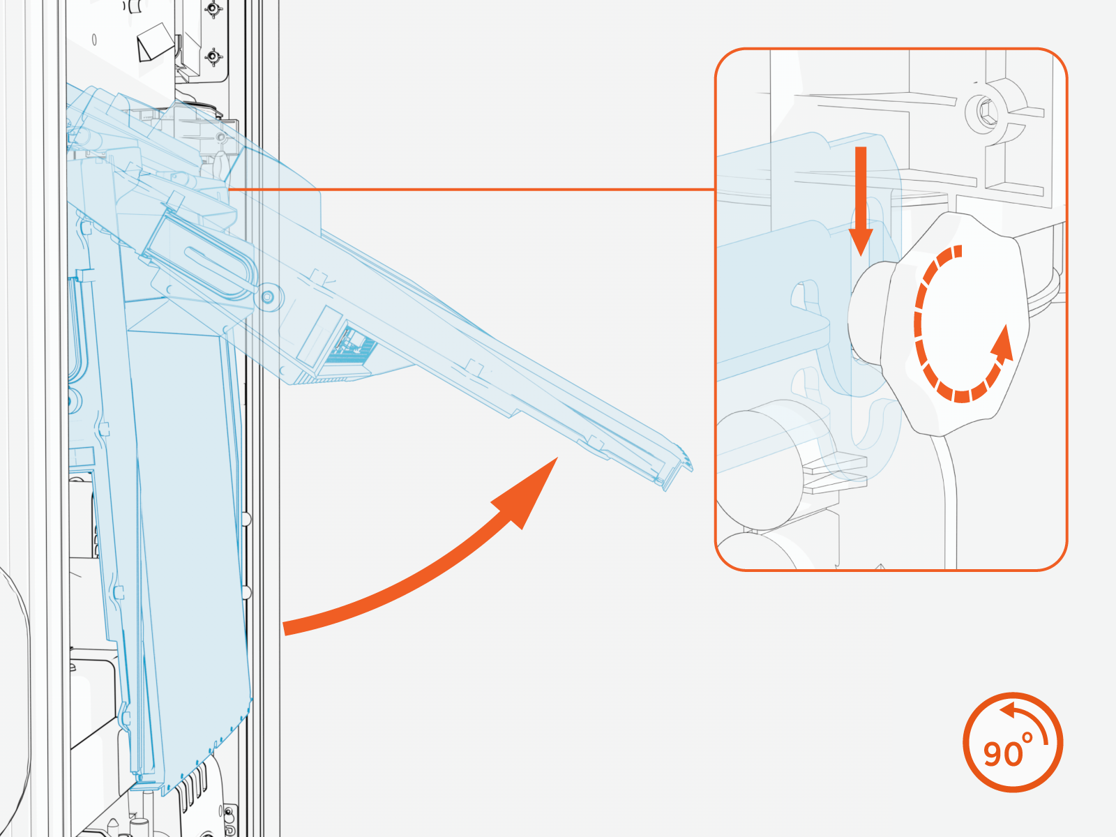
Allow the touchscreen to return to its lowest position vertically. Rotate the retention knobs clockwise to re-tighten.
The bottom edge and corners of the touchscreen are sharp. Take care when moving underneath the raised screen.
-
Locate the I/O expander under the touchscreen on the right side of the mount rail (a).
Observe the wire routing before removing the unit.
-
Each cable on the unit has a tab that locks it into position. Disconnect each of the cables by pushing its tab to release:
-
CAN A
-
CAN B
-
24 V
-
Hall Effects Sensors
-
Surge
-
Temp
-
E-Stop
-
-
Pull the two plastic tabs below the I/O expander unit to release the unit.
-
Pull the I/O expander unit upward to release it from the top rail, then toward you to remove it.
Replace the I/O Expander Unit
-
Hang the I/O expander unit temporarily on the top rail.
-
Reconnect its cables according to the labels on the unit cover.
-
Align cable routing behind the unit to ensure it can be pushed from the bottom of the unit on each side. Push until it snaps into place on the bottom rail.
Ensure all cables are flat against the rail bar and are not being pinched.
REVERSE THE ABOVE STEPS TO REPLACE THE TOP FRONT PANEL, LED DISPLAY, AND AREA LIGHT BAR.
Power On the Station
Once all cover panels are installed, power on the station. The on-screen Installation Wizard steps you through any required tasks to set up the station and verify that it can operate properly.
An Installation Wizard test checks that all cover panels are correctly installed and fully seated. Check the lower right corner of the screen for any error messages. If panel errors appear, match the panel letters to this illustration.
(a) Front bottom panel
(b) Middle vent panel
(c) Front top panel
(d) LED display
(e) Area light bar
(f) Rear bottom panel
(g) Rear middle panel
(h) Rear top panel
(i) Left extrusion
(j) Right extrusion
If any panel needs re-installation, review the procedures above to double-check that all panels are fully seated and that the edges of all signs are captured fully by the panels around them.